6-10 Configuration of the Drive System Rexroth IndraDrive Rexroth IndraDrive
DOK-INDRV*-SYSTEM*****-PR02-EN-P
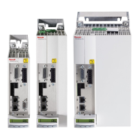
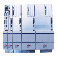
central supply via HCS02.1E-W0070 with assigned HNL01.1 mains
choke:
• 1 * HCS02.1E-W0070 (supplying device)
• 1 * HMS01.1N-W0054
• 1 * HMS01.1N-W0036
• 1 * HMS01.1N-W0020
• 1 * HMD01.1N-W0036
• 1 * HMD01.1N-W0020
• 2 * HMD01.1N-W0012
sum of type currents (to be supplied): 270
sum of drive controller axes: 12
Note: HMS01 / HMD01 are generally mounted to the right.
Mount the required HAS04 at the HCS02 mounted to the left.
Place the additional capacitance module HLC01.1 at the
junction between HCS02.1 and HMS01.1 or HMD01.1.
CAUTION
Damage to the drive controller!
⇒
Do not exceed allowed peak and continuous powers
in the DC bus.
Example
 Loading...


