Rexroth IndraDrive Control Circuits for the Mains Connection 11-15
DOK-INDRV*-SYSTEM*****-PR02-EN-P
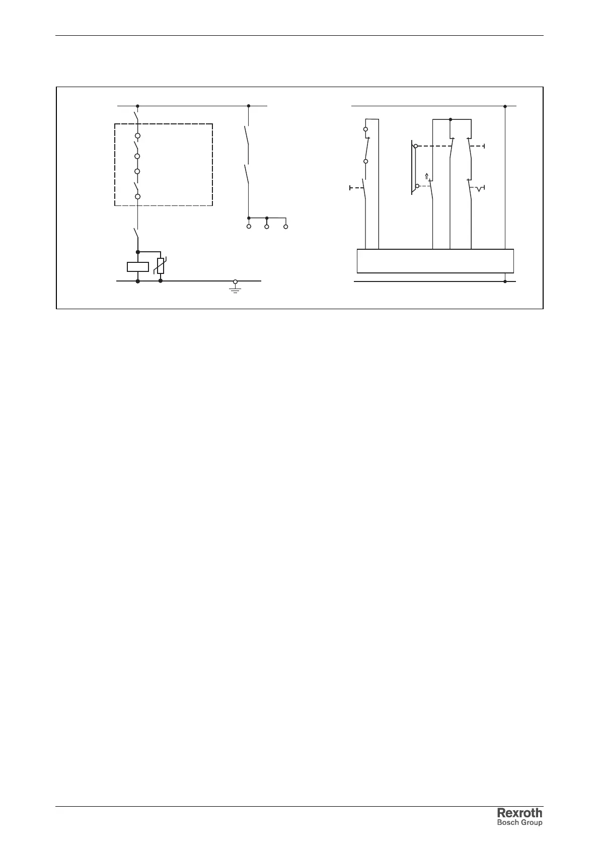
Preferred Wiring of E-Stop Circuit
hlb_notaus_kette.fh7
12
+24V
+/- 5%
K4
K4
0V
U
S1
S4
S11
S12
K1
A10
K1
RF
Bb
HMV01.1E/
HMV01.1R
X33/4
X33/3
X31/4
UD
X31/3
AF
AF
AF
S5
X33/1
X33/2
A10
A10: E-Stop relay
AF: drive enable of drive controllers
Bb: readiness for operation of drive controllers
K1: mains contactor in supply unit
K4: control of drive enable
S1: E-Stop
S2: axis end position
S4: power Off
S5: power On
S11/S12: safety door monitor
Fig. 11-9: Preferred wiring of E-Stop circuit