10-4 Requirements to the Mains Connection Rexroth IndraDrive
DOK-INDRV*-SYSTEM*****-PR02-EN-P
I
K
results in the case of a short circuit at the point of power supply
connection. It is calculated as follows:
k
N
k
X
U
I
3
=
X
K
: system impedance
U
N
: mains voltage
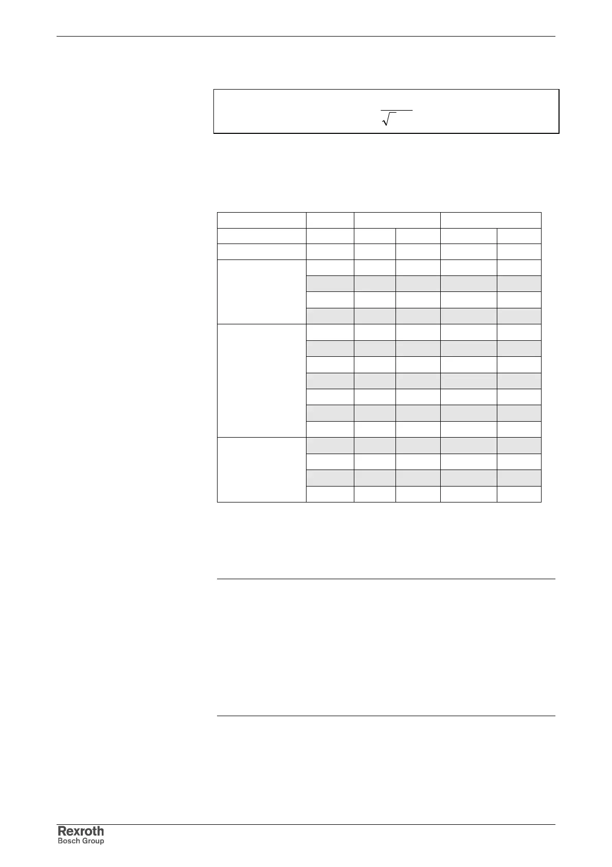
Fig. 10-7: Mains short-circuit current
We basically distinguish the following mains, graded according to mains
short-circuit power and system impedance:
U
N
=400 V U
N
=480 V
Classification
S
k
X
k
L
k
X
k
L
k
MVA mOhm uH mOhm uH
200 0,80 2,55 1,15 3,67
150 1,07 3,40 1,54 4,89
100 1,60 5,09 2,30 7,33
1
rigid mains
50 3,20 10,19 4,61 14,67
40 4,00 12,73 5,76 18,33
30 5,33 16,98 7,68 24,45
20 8,00 25,46 11,52 36,67
15 10,67 33,95 15,36 48,89
10 16,00 50,93 23,04 73,34
5 32,00 101,86 46,08 146,68
2
semi-rigid mains
4 40,00 127,32 57,60 183,35
3 53,33 169,77 76,80 244,46
2 80,00 254,65 115,20 366,69
1 160,00 509,30 230,40 733,39
3
non-rigid mains
0,6 266,67 848,83 384,00 1222,31
S
k
: short-circuit power of the mains
X
K
: system impedance
L
k
: inductance of mains phase
Fig. 10-8: Mains classified according to mains short circuit power and mains
internal resistance
Note: The minimum inductances of the mains connection specified
in the respective Project Planning Manual refer to the
inductances L
k
mentioned above.
The specified minimum inductances protect the drive
controllers (especially the DC bus capacitances) during
operation at mains with low impedance and high mains short-
circuit power.
With a specified minimum inductance of 40 µH, for example, it
is necessary to use a mains choke at mains with U
N
= 400 V
S
K
>10MVA.
Mains Classes