7-2 Arranging the Components in the Control Cabinet Rexroth IndraDrive
DOK-INDRV*-SYSTEM*****-PR02-EN-P
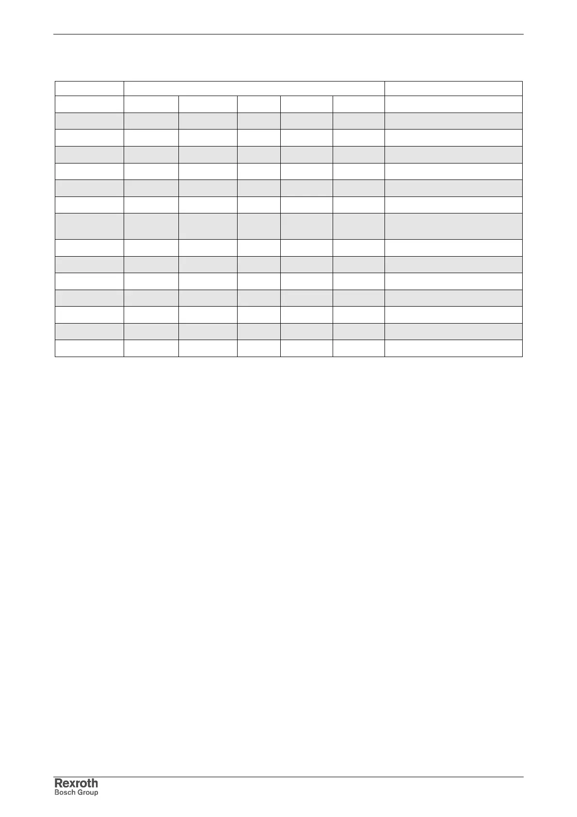
Allowed positions of normal use and mounting positions with reduction
factor
Component Mounting position / reduction factor Notes
G1 G2 G3 G4 G5
HCS02.1E
100% -- -- -- --
HCS03.1E
100% -- -- -- --
HMV01.1E
100% -- -- -- --
HMV01.1R
100% -- -- -- --
HMS01.1
100% -- -- -- --
HMD01.1
100% -- -- -- --
NFD03.1
100% 100% 80% 100% 80%
reduction of maximum allowed
continuous current
HNF01.1
100% -- -- -- --
HNL01.1
100% 100% 100% 100% 100%
HLB01.1C
100% -- -- -- --
HLB01.1D
100% -- -- -- --
HLC01.1C
100% -- -- -- --
HLC01.1D
100% -- -- -- --
HLR01.1
100% -- -- -- --
-- not allowed
Fig. 7-2: Allowed positions of normal use and mounting positions
Example "NFD03.1 in position of normal use G5":
In position of normal use G5 the mains filter NFD03.1 may only be loaded
with 80% of the maximum allowed continuous current. The reduced load
must be guaranteed by the application.