12-6 Connections of the Components in the Drive System Rexroth IndraDrive
DOK-INDRV*-SYSTEM*****-PR02-EN-P
CAUTION
Risk of damage!
⇒
If the total power of the lower row when using HMV
supply units is more than 60 kW, the DC bus
connection has to be realized to both sides (DC bus
connections both to the left and to the right).
Cable Routing to the Left
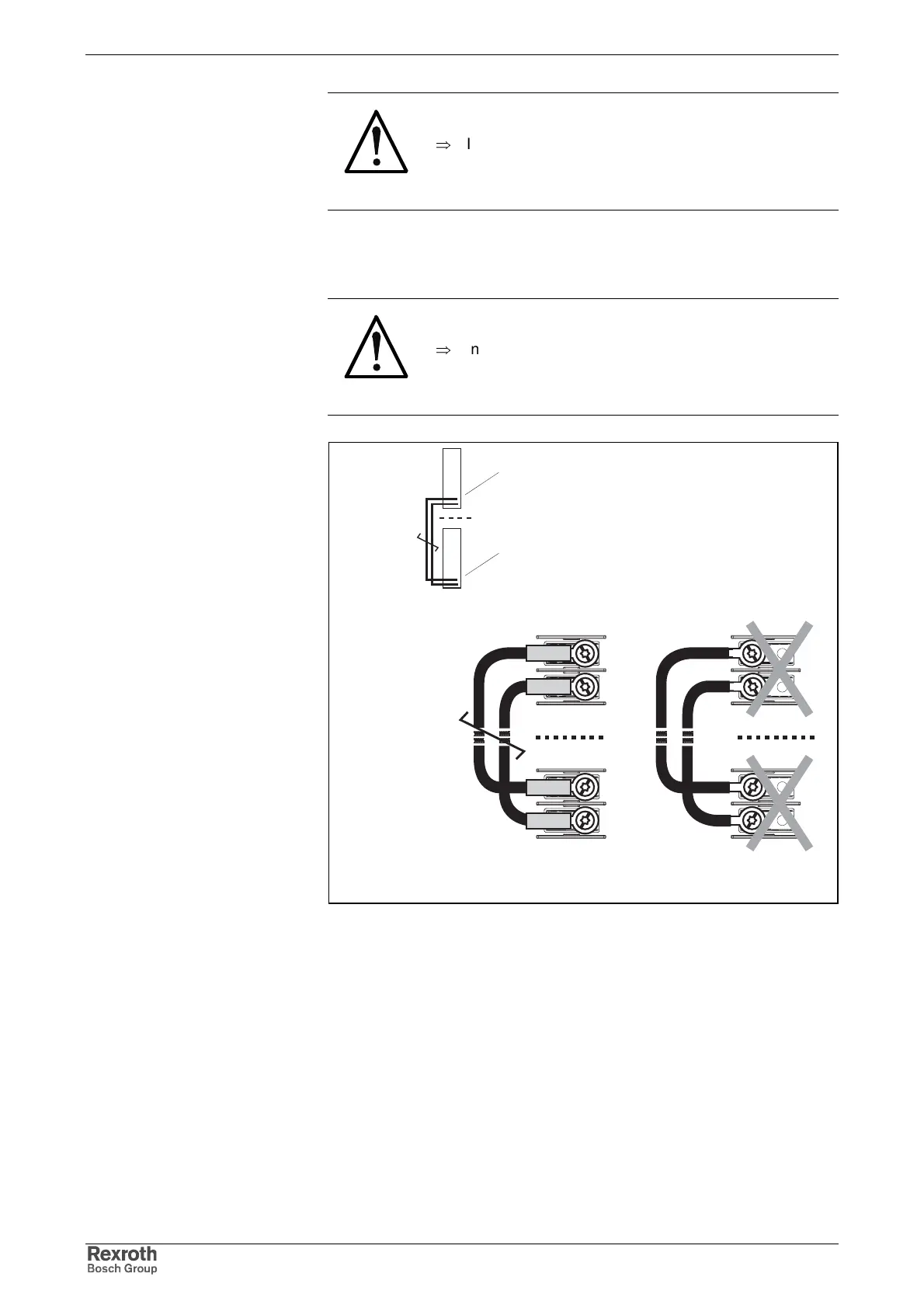
CAUTION
Damage caused by voltage arcing!
⇒
Insulate ring terminals and connecting lines with a
heat-shrinkable sleeve. Afterwards only strip the
insulation of the contact surface of the ring terminal.
Realize connections according to figure.
DC bus nach links_1f4
correct incorrect
device 1
(DC bus connection)
device 2
(DC bus connection)
device 1
(DC bus connection)
device 2
(DC bus connection)
Fig. 12-6: DC bus connections for cable routing to the left