FAX UNIT
B404 1-4 SM
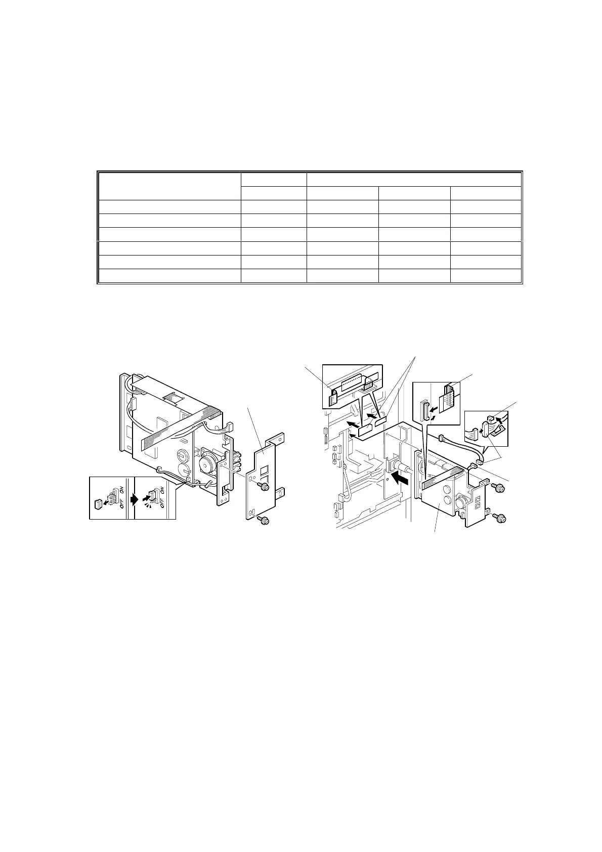
4. Connect the following pins on switch TB1 on the FCU and TB1 – TB3 on the
NCU. After that, replace the NCU cover.
NOTE: European and Asian models only
Individual Switch Settings:
FCU NCU
Country
TB1 TB1 TB2 TB3
CTR21, Israel 2-5 2-3 OFF ON
Poland 2-5 2-3 ON OFF
Australia 2-5 1-2 OFF ON
New Zealand 2-5 1-2 ON OFF
Malaysia, South Africa 3-4 1-2 OFF ON
Asia and others 3-4 1-2 ON OFF
NOTE: It is necessary to change the country code in both system switch 0F
and NCU function 08-0.
5. Change the battery switch [A] on the FCU to ON as shown.
6. Attach the bracket [B] (2 screws) as shown.
7. Attach the two mylars [C] to the rear bracket of the mainframe as shown.
8. Connect the relay cable [D] to the PSU first, then connect it to the FCU-PSU
cable [E], then secure cable [D] with clamp [F], then install the fax unit [G] (2
screws).
9. Run the flat cable [H] through between the mylars and the rear bracket of the
mainframe, then connect the flat cable [H] to the BiCU.
NOTE: If the printer option will be installed at the same time, run the flat cable
[H] through the core [I] (contained in the printer option) as shown.
10. Replace the rear cover.
B405I104.WMF
B405I103.WMF
[A]
[B]
[C]
[D]
[E]
[G]
[H]
[H]
[I]
[I]
[F]