Roche Diagnostics
Instructions for Use · Version 13.0 35
cobas b 123 POC system 2 General description
System components
Name plate Refer to Symbols used on the instrument (p. 8) to find the meaning of the symbols
used on the name plate.
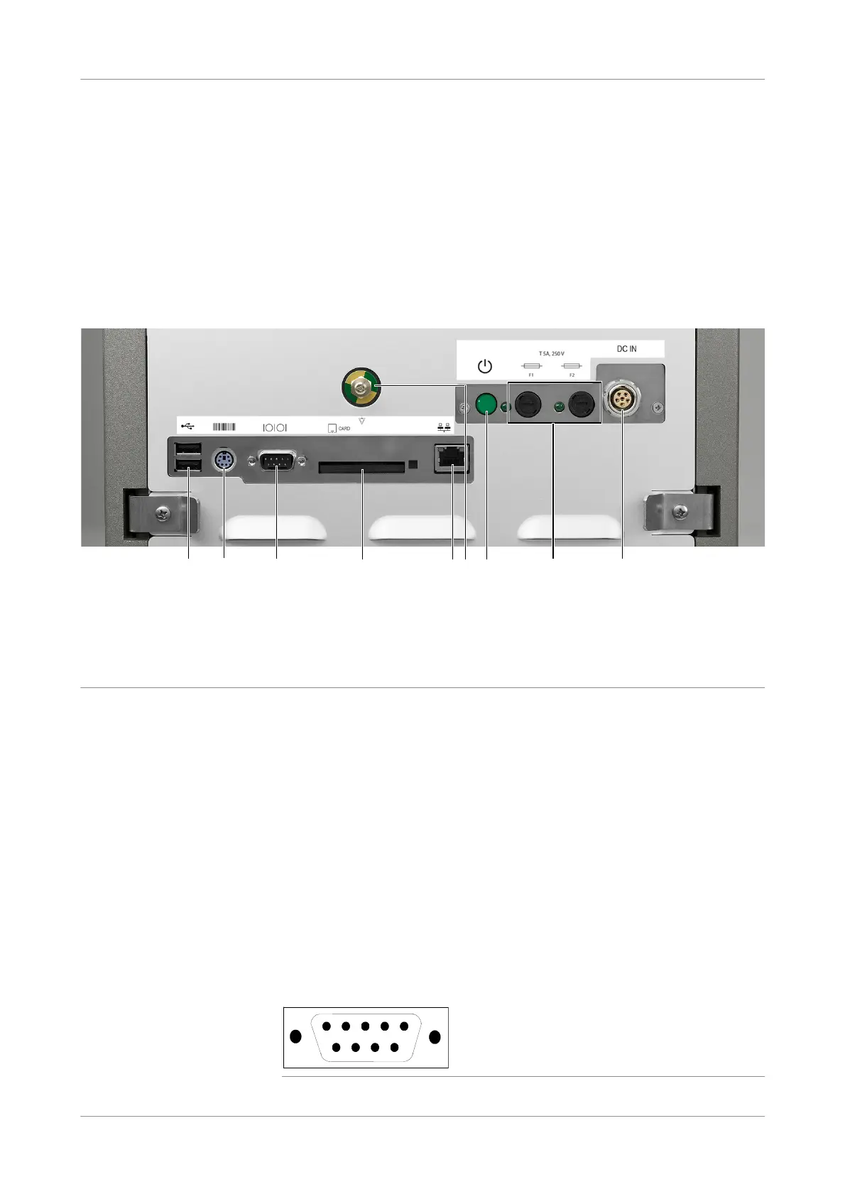
Interfaces: Hardware version 1
u Hardware versions (p. 30)
Figure 2-8 Interfaces: Hardware version 1
o 2 USB ports
o Barcode scanner: PS/2 DIN - 6p female socket
o 1x RS 232 interface (e.g. external ticket printer)
o 1x CompactFlash card slot
o 1x 100BaseTX Ethernet (RJ45)
o 2x LED: control lamps for supply voltage
o 2x fuses: 5A slow blow 250 V
o Power supply: connection socket for external power supply
Each voltage supply circuit has a “Power ON” display (green LEDs next to the fuses).
The LEDs are wired into the circuit downstream of the fuses.
RS 232 interface assignment
(Hardware version 1 only)
RS 232 interface connections may be used to establish connections with other
devices, such as external ticket printers. 9-pin SUBMIN D is available for these
interface connections.
Figure 2-9 RS 232 interface assignments
(1) IEC320-EN60320/C13: Plugs and Socket-Outlets for Household and Similar Purposes
(2) Standard for the US, Canada, and Japan.
A USB ports F Equipotential bonding plug
B Barcode scanner G Button (on/off)
C External ticket printer (RS 232) H Status LEDs (2x) and fuses (2x) (Fuse 5A slow 250V)
D CompactFlash card I Power supply
E Network: Ethernet (RJ45)
A
B
C
D
E
F
G
H
I
1
2
3 4
6
7 9
8
5
 Loading...