Setting Mode Setting Using Calibration Password
Examples:
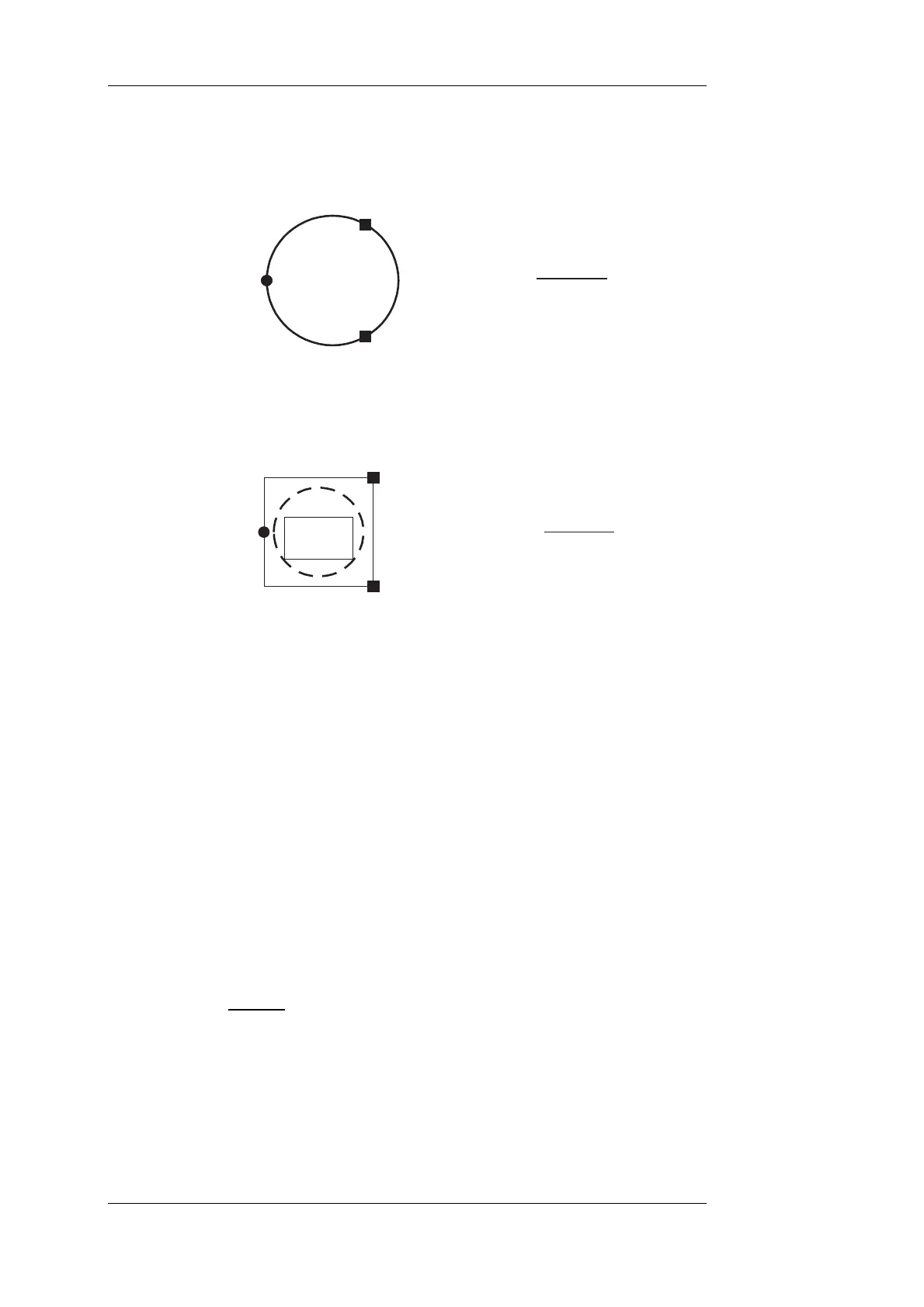
A hopper scale is placed on one load cell and two pivots. If load cells are arranged
rotation-symmetrically, and the two pivots around a round-shaped hopper with mid
center of gravity ( load carrier to 3 x 120°) the load is distributed to 1/3 each:
33,33 %
Wägezelle
Load cell
Capteur
Cella pesatrice
33,33 %
Festlager
Pivot
Palier
Supporto fisso
33,33 %
Festlager
Pivot
Palier
Supporto fisso
F
mech
=
100 %
33,33 %
=3
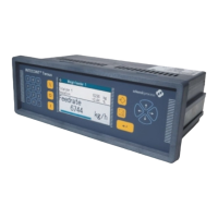
With a rectanglular hopper or a round-shaped hopper in a symmetrical weighing
frame, the result is different (even if the latter is square and totally symmetric):
50 %
Wägezelle
Load c lle
Capteur
Cella pesatrice
%
Festlager
Pivot
25 %
Festlager
fisso
F
mech
=
25
Palier
Supporto fisso
Pivot
Palier
Supporto
100 %
50 %
=2
Behälter
his load distribution is caused by the different spacing of
ral
2 results.
erly considered.
e pers with unsymmetrical load distribution, must be
e consideration or at best calibrated with the use
of a pre- lled into hopper.
TTENT
position
5.4.2.9 Parameter 'Calibration Factor'
Display:
Hopper
Récipient
Recipiente
T
• load cells (1/2 side length)
• pivots (1/2 diagonal)
from hopper centre of gravity, i.e. the three support points do not form any equilate
triangle. For theoretical calibration, value
When designing the load cell, its load must be prop
Any oth
derived
r case, e.g. rectangular hop
ither from precise geometric
weighed medium (liquid) fi
A ION: Upon calibration with weights, ensure that the mid center of gravity
is precisely kept.
F-calib. 1.00000
Input: Any value from 0.9 to 1.1
Default = 1
Enter
tterings in load cell characteristic values, or scale
mech cteristic value.
yste ibration.
F-cal
value without unit.
Considers F-calib. sca
anics total chara
S m acquires parameter value during range cal
ib. = Test weight / displayed weight
BV-H2313 GB 0630 DISOMAT
®
Opus – Operating Manual
- 78 - © Schenck Process GmbH, Darmstadt