Display Device or configura‐
t
ion
Meaning
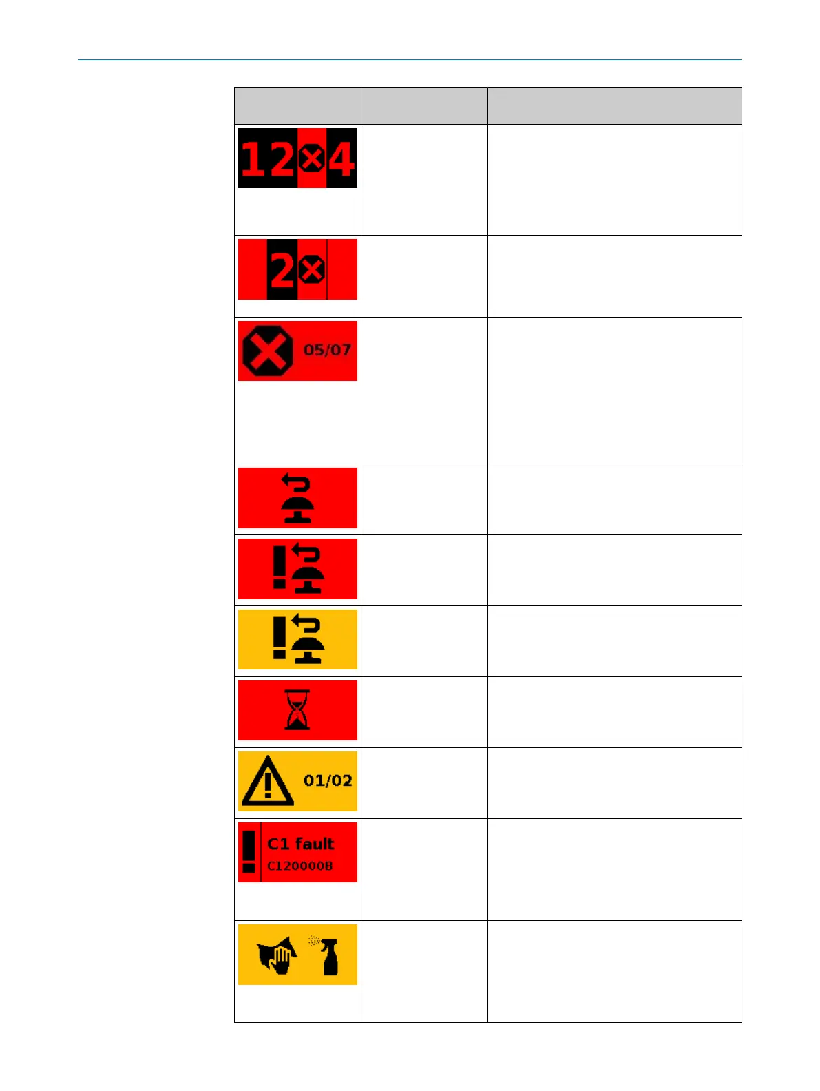
Devices and configu‐
r
ations with 2 to 4
configured safety out‐
puts
The protective field in position 3 is interrupted
or there is a warning field in the active monitor‐
ing case. The associated safety output is in the
OFF state.
Safety outputs for which no field is interrupted
and which are in the ON state are marked with
their number.
Devices and configu‐
r
ations with 2 to 4
configured safety out‐
puts
Cut-off paths in which no protective field is
located are not marked. The associated safety
output is in the OFF state.
A non-safety-related output can still be in the
ON state, e.g. if a warning field is free.
Devices and configu‐
r
ations with more than
4 configured safety
outputs
For one or more cut-off paths, the following
applies: the protective field is interrupted or
there is a warning field in the active monitoring
case. The associated safety outputs are in the
OFF state.
•
Left digit: the number of safety outputs in
the OFF state
•
Right digit: the number of configured safety
outputs
Configuration with
r
estart interlock
Protective field is clear, reset can take place.
Configuration with
r
estart interlock
Reset button pressed Safety output in the OFF
state.
Configuration with
restart interlock
Reset button pressed Safety output in the ON
state.
Configuration with
aut
omated restart
after a time
Protective field is clear, configured time to
restart expires.
Configuration with at
le
ast one warning field
Warning field interrupted (left column: num‐
ber of interrupted warning fields, right col‐
umn: number of warning fields in the current
monitoring case).
Display flashes
All devices and config‐
ur
ations
Fault. All safety outputs in the OFF state. Addi‐
tional information: see "Fault indication on the
display", page 151.
Display flashes
All devices and config‐
ur
ations
Contamination warning. Check the optics cover
for damage. Clean the optics cover.
9 OPERATION
140
O P E R A T I N G I N S T R U C T I O N S | microScan3 – PROFINET 8021219/1ELL/2022-01-21 | SICK
Subject to change without notice