3. Prepare the mains and motor cables for connection in accordance with the table below.
Inverter Connection Dimensions Explanation
A B C
1)
D
FSA Mains cable 10 mm 60 mm - 90 mm
Motor cable 10 mm 60 mm 10 mm 60 mm
FSB Mains cable 10 mm 60 mm - 50 mm
Motor cable 10 mm 50 mm 10 mm 40 mm
FSC Mains cable 10 mm 50 mm - 70 mm
Motor cable 10 mm 50 mm 10 mm 40 mm
1)
Cable shield
① Bolting plate
4. Assemble the cable glands with the prepared cables and EMC cable glands for the control
cables.
5. Seal any unused bushings with a rubber sleeve.
6. Secure the bolting plate to the inverter enclosure. Tightening torque: 2 Nm
Make sure that the seal of the bolting plate is not damaged.
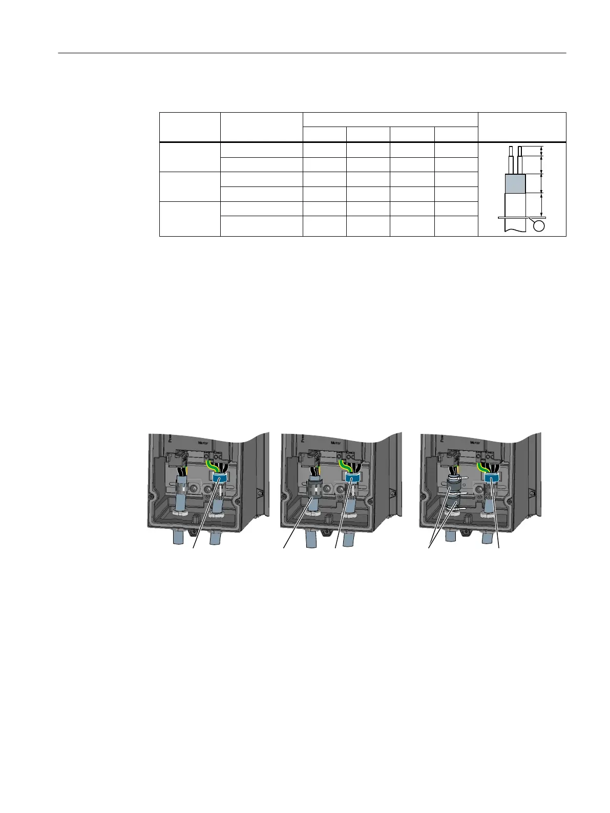
7. Where necessary, fit the supplied ferrite ring onto the motor cable.
Ferrite rings are required to be able to comply with the limit values of IEC 61800-3, Category
C1 with reference to grid-bound interference voltages when using Power Modules with
integrated line filters.
If you use cables > 25 m, the requirements of Category C1 are no longer satisfied.
JUD\IHUULWHULQJV
IRUWKHOLQHFDEOH
%OXHIHUULWHULQJIRU
WKHPRWRUFDEOH
%OXHIHUULWHULQJIRU
WKHPRWRUFDEOH
%OXHIHUULWHULQJIRU
WKHPRWRUFDEOH
JUD\IHUULWHULQJ
IRUWKHOLQHFDEOH
)6&)6$)6%
Figure 4-14 Ferrite rings for the mains and motor cables
Installing
4.4 Connecting the line supply and motor
Converter with the CU230P-2 Control Units
Operating Instructions, 09/2017, FW V4.7 SP9, A5E34257946B AE 91

 Loading...


