Function Manual
198 01/2017
Appropriate measures must be taken to ensure that the motor does not undesirably move once the energy feed has been
disconnected, e.g. against coasting down.
If two power transistors simultaneously fail in the power unit (one in the upper and one in the lower bridge), then this can
cause brief momentary movement.
The maximum movement can be:
Synchronous rotary motors: Max. movement = 180 ° / No. of pole pairs
Synchronous linear motors: Max. movement = pole width
Note
Closing delay of the holding brake
The closing signal (low level) of the holding brake is output 30 ms after the STO is triggered.
Preconditions for using the STO function
When use the STO function, the following preconditions should be fulfilled:
● Each monitoring channel (STO1 and STO2) triggers safe pulse suppression with its switch off signal path.
● If a motor holding brake is connected and configured, the connected brake is not safe because there is no safety function
for brake, such as safe brake.
Behaviors of the STO function
High level High level Safe The servo motor can normally run when you power on the servo
Low level Low level Safe The servo drive starts up normally but the servo motor cannot
Alarm occurs and servo motor coasts down.
Alarm occurs and servo motor coasts down.
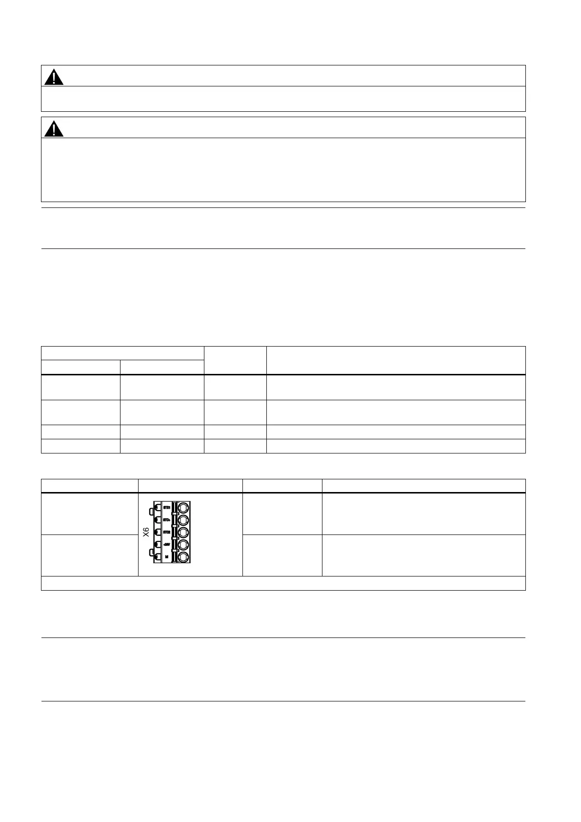
Control circuit interfaces - drive side
Safe Torque Off (STO)
interfaces
STO 1
STO +
STO 1: coast down
STO +: 24 VDC
Control power input
interfaces
1)
+24 V
M
Power supply 24 VDC (without brake: -15% to
+20%, with brake: -10% to +10% )
Power supply 0 VDC
Maximum connectable cross-section: 1.5 mm
2
1)
Maximum current consumptions without brake power supply and with brake power supply are respectively 1 A and 3 A.
Note
Using the STO function
The STO1, STO+ and STO2 are short con
nected at the factory setting.
When the STO function is to be used, you must remove the short
-circuit stick before connecting the STO interfaces. If you
do not need to use it any more, you must reinsert the short
-circuit stick; otherwise, the motor will not run.
 Loading...


