Function Manual
01/2017
41
Jerk limitation can be determined for specific axes. The acceleration response corresponds with the SOFT acceleration
profile of path-related jerk limitation. This limitation cannot be deselected for the axes in the relevant modes.
The axes for which jerk limitation is to be programmed can be selected with MD32420 JOG_AND_POS_JERK_ENABLE.
The permissible axis-specific maximum jerk is stored in MD32430 JOG_AND_POS_MAX_JERK.
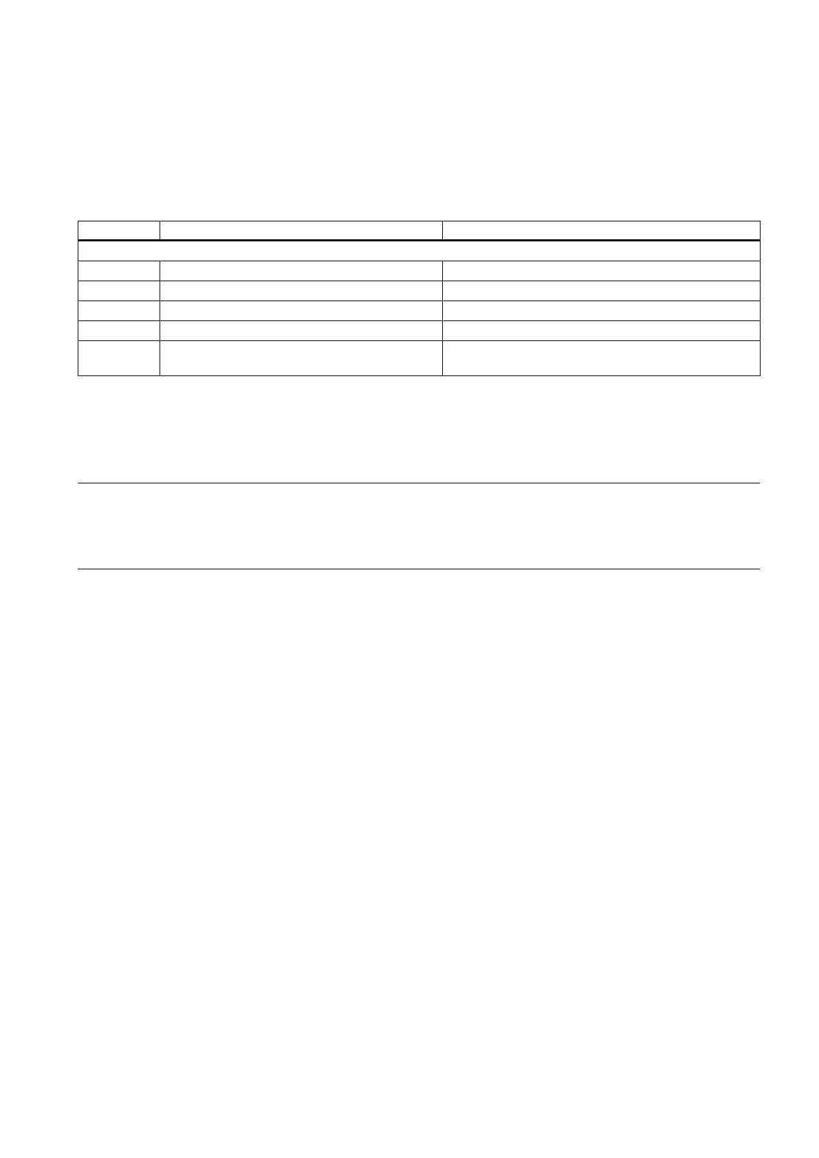
Machine data
Enabling axis-specific jerk limitation
32430 JOG_AND_POS_MAX_JERK Axis-specific jerk
Maximum axis-specific jerk during path movement
32432 PATH_TRANS_JERK_LIM Maximum axis-specific jerk during path movement at
Note
If the corresponding option is activated without a valid license, alarm 8081 "%1 option(s) that has (have) not been licensed
using a license key was (were) s
et" is output. It will not be possible to operate the machine as normal.
For information on operations relating to "Setting (an) option(s)", please refer to the chapter titled "
Licensing in the
ERIK 808D/SINUMERIK 808D ADVANCED (Page 325)".
Gantry axes are mechanically grouped machine axes. Because of this mechanical coupling, gantry axes are always
traversed in unison. The control occurs through the "gantry axes" function.
The machine axis that is directly traversed is called the leading axis. The machine axis that is traversed in synchronism with
it is called the synchronized axis. Together, the leading axis and synchronized axis form a gantry axis grouping.
The difference between the actual positions of the leading axis and synchronized axis is monitored continuously. When the
actual position value of the synchronized axis deviates too much from that of the leading axis, the control automatically
brings all axes in the gantry grouping to a standstill in order to prevent any damage to the machines.
Two feed drives are required to traverse the gantry on large gantry-type milling machines, i.e. one drive with its own position
measuring system on each side. Owing to the mechanical forced coupling, both drives must be operated in absolute
synchronism to prevent canting of mechanical components.
A gantry axis grouping consisting of a leading axis and synchronized axis can be defined.
"Gantry axes" function
Application
On large gantry-type milling machines, various axis units (e.g. gantry or crossbeam) are moved by a number of drives, which
are mutually independent. Each drive has its own measuring system and thus constitutes a complete axis system. When
these mechanically rigidly-coupled axes are traversed, both drives must be operated
in order to
prevent canting of mechanical components (resulting in power/torque transmission).

 Loading...


