Function Manual
42 01/2017
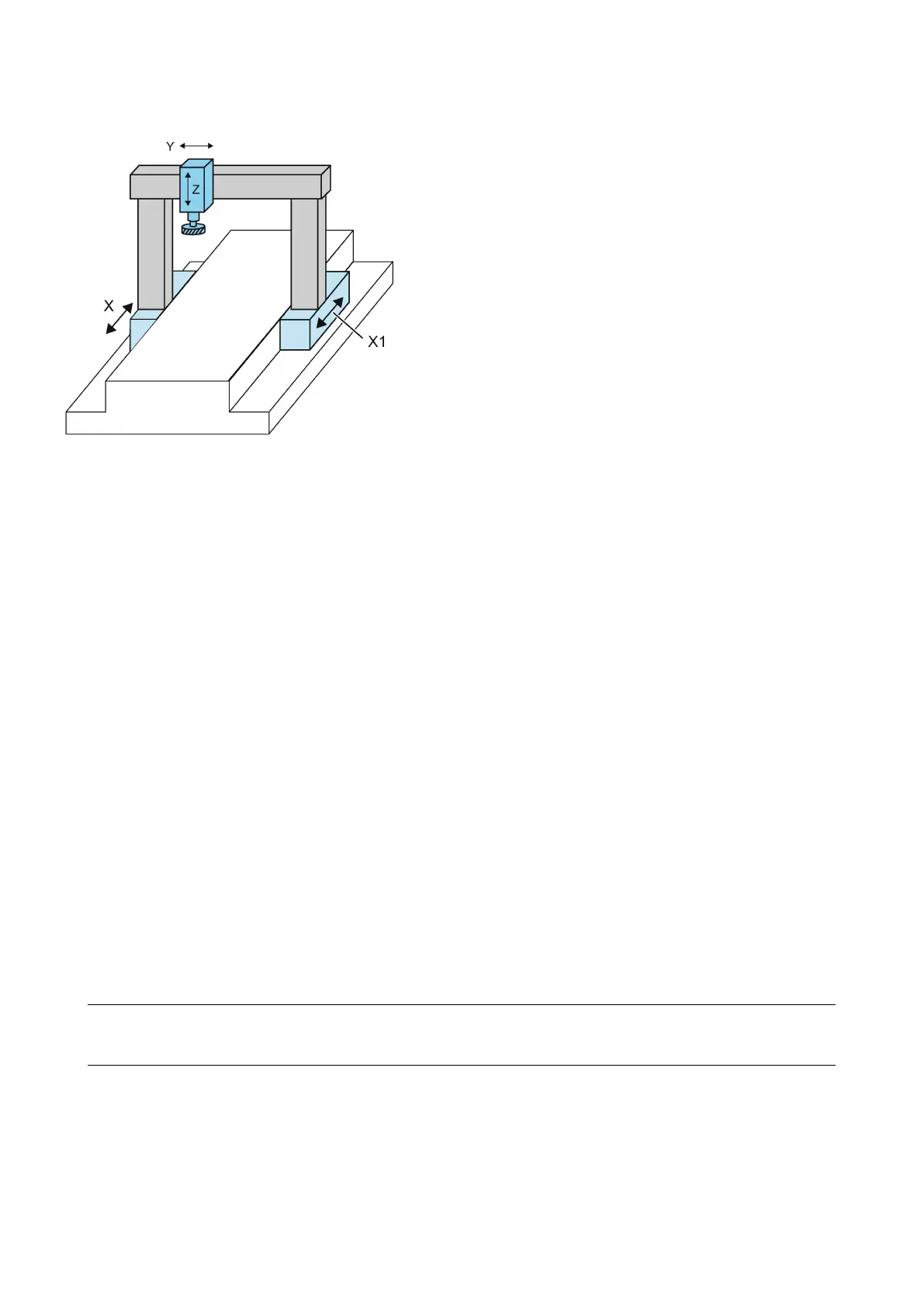
Example: Gantry-type milling machine with a gantry axis grouping (X and X1)
The purpose of the "gantry axes" function is to control and monitor machine axes which are rigidly coupled in this way.
The following terms are frequently used in this functional description:
Gantry axes comprise one pair of axes, the leading axis and the synchronized axis. As these axes are mechanically coupled,
they must always be traversed simultaneously by the NC. The difference between the actual positions of the axes is
monitored continuously. The axes in a gantry grouping are either all linear axes or all rotary axes.
A total of
gantry connection can be defined. Each gantry grouping consists of
leading axis and
synchronized
axis.
The gantry axis grouping defines which synchronized axis is controlled by which leading axis, based on machine data
settings. The leading axis and synchronized axis cannot be traversed separately.
The leading axis is the gantry axis that exists from the point of view of the operator and programmer and, thus, can be
influenced like a standard NC axis. The axis name of the leading axis identifies all axes in the gantry axis grouping.
A synchronized axis is the gantry axis whose set position is continuously derived from the motion of the leading axis and is,
thus, moved synchronously with the leading axis. From the point of view of the programmer and operator, the synchronized
axis "does not exist".
Conditions for a gantry grouping
● A gantry grouping must not contain a spindle.
● A synchronized axis must not be addressed by a transformation.
● A synchronized axis must not be the slave axis in another type of axis coupling.
● A synchronized axis must not be defined as the leading axis in another axis grouping.
Note
Each axis in the gantry grouping must be set so that it can take over the function of the leading axis at any time, i.e.
matching velocity, acceleration and dynamic r
esponse settings.
The control performs a plausibility check on the axis definition.
 Loading...


