Function Manual
324 01/2017
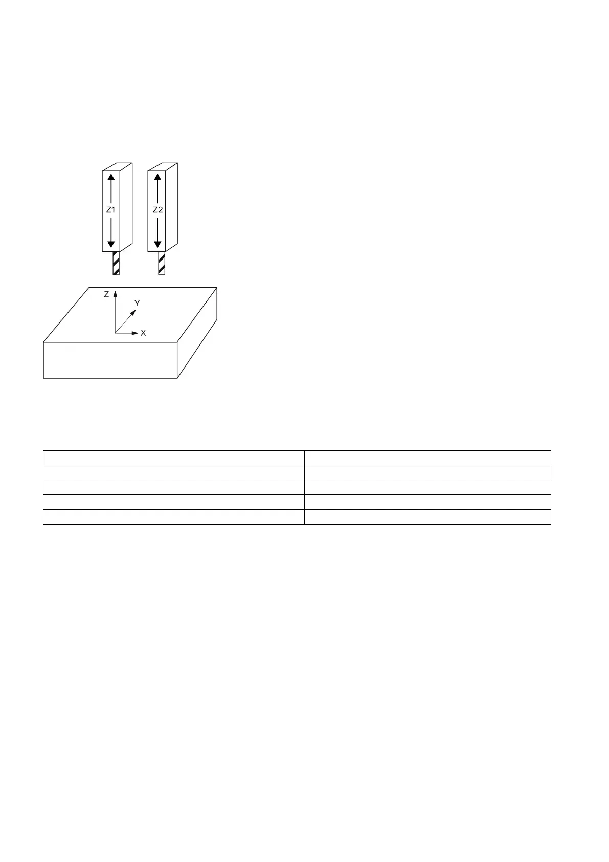
Which channel axes are assigned to the geometry axis of the channel can be specified with the GEOAX command.
As shown in the figure below, you can use axis Z1 as the third geometry axis named axis Z, which, together with axes X1
and Y1, form a geometry coordinate system used for interpolatory compensation. Alternatively, you can use axis Z2 as the
third geometry axis named axis Z, which also, together with axes X1 and Y1, form a geometry coordinate system used for
interpolatory compensation. In this way, axes Z1 and Z2 can be alternatively used as geometry axis Z in a part program.
Machine data for switching geometry axes
The workpiece geometry is described by a coordinate system that is formed by the geometry axes. A channel axis is
assigned to each geometry axis and a machine axis is assigned to each channel axis.
The required assignment for switching geometry axes is as follows:
MD10000 AXCONF_MACHAX_NAME_TAB
MD20050 AXCONF_GEOAX_ASSIGN_TAB
Assignment of geometry axis to channel axis
MD20060 AXCONF_GEOAX_NAME_TAB
Geometry axis names in channel
MD20070 AXCONF_MACHAX_USED
Valid machine axis numbers in channel
MD20080 AXCONF_CHANAX_NAME_TAB
Channel axis names in channel
The GEOAX command is formatted as follows:
GEOAX(n, channel axis name)
Activation of the geometry axis switchover
; Deactivation of the geometry axis switchover
n = 1 to 3: number of the geometry axis to which a channel axis is assigned
Channel axis name: name of the channel axis that is assigned to a geometry axis
● MD10000[4] = MZ2
● MD20080[0] = X1
● MD20080[1] = Y1
● MD20080[2] = Z1
● MD20080[4] = Z2

 Loading...


