Function Manual
90 01/2017
Only one ASUP can be started at one time. If the start signal for both ASUPs is to be set to logical 1 in a PLC cycle, the
ASUPs are started in the sequence INT1 and then INT2.
The start signal must be set to logical 0 by the user once the ASUP has been completed or if an error has occurred.
The control system provides two default ASUPs for the PLC. ASUP1 is used for manual tool changing and ASUP2 is used
for the manual machine of the workpiece on a turning machine with the Manual Machine Plus function.
You can also use your own ASUPs as required. To do so, you must first place your programs (PLCASUP1.SPF and
PLCASUP2.SPF) in the manufacturer cycle directory (N:\CMA), and then set "PI index" (DB1200.DBB4001) to 1 (ASUP1)/2
(ASUP2).
Note
The call of the ASUP PI service must have been completed before an ASUP m
ay be started.
The initialization is performed via the ASUP PI service.
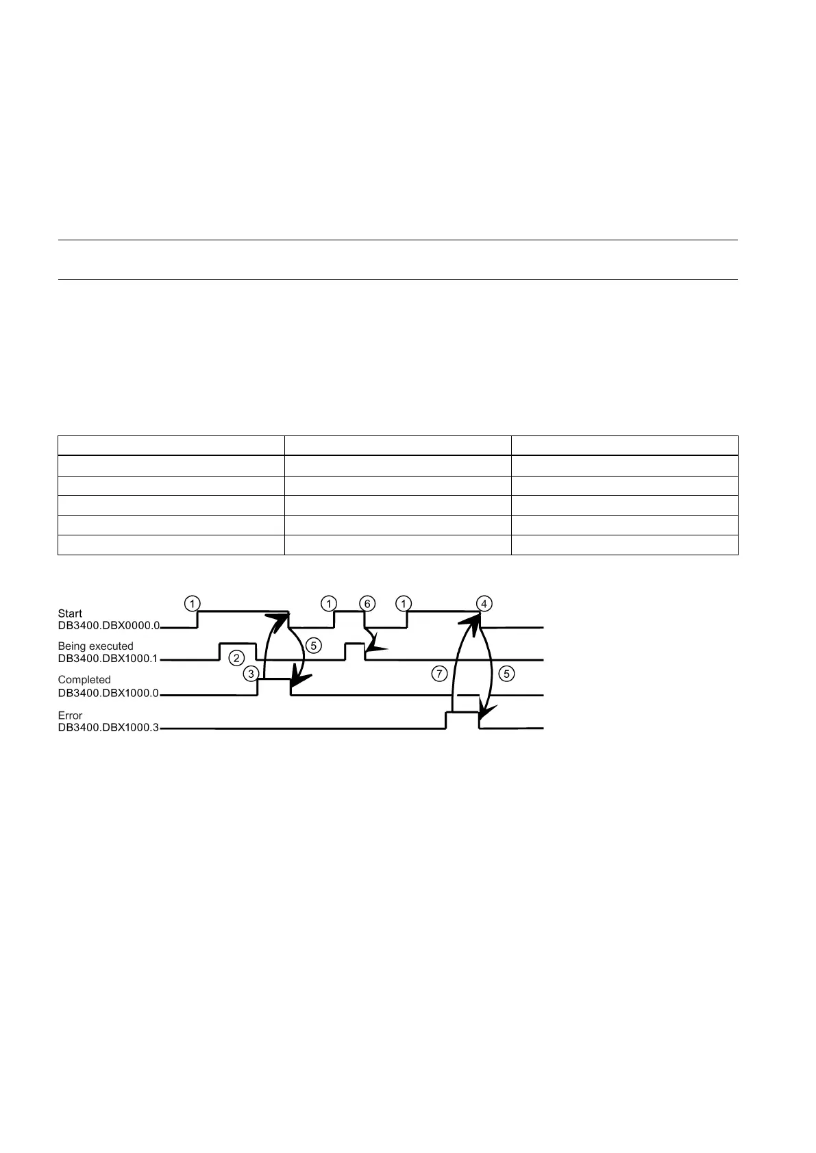
The time sequence of an ASUP is shown in the following pulse diagram in the example of PLCASUP1.SPF. You can see
from the table which interface signals are of relevance for PLCASUP2.SPF.
For the assignment of the signals to the pulse diagram, see the table below:
Interrupt no. not allocated
Pulse diagram for PLCASUP1_SPF:
Function activation via positive edge of Start
Positive acknowledgment: ASUP ended
Reset function activation after receipt of acknowledgment
Signal change through PLC
Not permitted. If function activation is reset prior to receipt of acknowledgment, the output signals are not updated
without the operational sequence of the activated function being affected
Negative acknowledgment: Error has occurred
The behavior of the ASUP can be influenced via the following standard machine data.
● MD11602 ASUP_START_MASK (ignore stop reasons for ASUP)
The machine data specifies which stop reasons are to be ignored for an ASUP start.
Recommended: MD11602 = 'H7'
● MD11604 ASUP_START_PRIO_LEVEL (priority, as of which MD11602 is effective)

 Loading...


