P3: Basic PLC Program for SINUMERIK 840D sl
13.13 Block descriptions
Basic Functions
1018 Function Manual, 09/2011, 6FC5397-0BP40-2BA0
FB 1-Parameter "ExtendAlMsg"
With the activation of the parameter a new structuring of the DB 2 becomes effective (see "Interface PLC/HMI
[Page 868]"). Upon activation the bit fields are available to the user for the disable and halt signals, which do not
generate any alarms, messages. As a result, the user need not implement the aforesaid measures. The desired
functionality is given automatically by a simple setting, resetting of signals in the new DB 2 areas.
The error and the operating messages are stored by the user in data block DB2 (see description of DB2 in the
lists of interface signals).
Declaration of the function
STL Representation
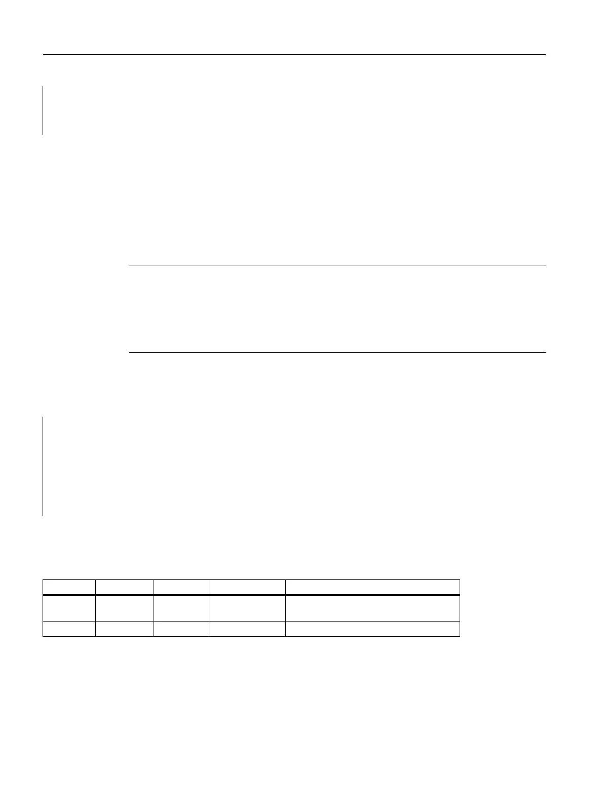
Description of formal parameters
The table below lists all formal parameters of the AL-MSG function.
to DB 21;
s dbx 6.0; //Setting the blocking condition,
//Resetting is done via FC AL_MSG,
//if M 50.0 outputs the signal "0".
Note
In DB 2, a "1" signal must be present for several OB1 cycles to ensure that a message can
also be displayed on the HMI. There is an upper limit for the number of interrupts and
messages that can be pending at the same time. This upper limit is dependent on the PLC
CPU. On PLC 317-2DP, the upper limit for messages pending simultaneously is 60.
See also Parameter Manual (Lists, Manual 2), chapter on PLC Alarms / Messages
FUNCTION FC 10 : VOID
// NAME: AL_MSG
VAR_INPUT
ToUserIF : BOOL ;
Ack : BOOL ;
END_VAR
END_FUNCTION
Signal Type Type Range of values Remark
ToUserIF I BOOL 1 = Transfer the signals to user interface
every cycle
Ack I BOOL 1 = Acknowledge error messages.

 Loading...


