W1: Tool offset
18.4 Tool cutting edge
Basic Functions
1450 Function Manual, 09/2011, 6FC5397-0BP40-2BA0
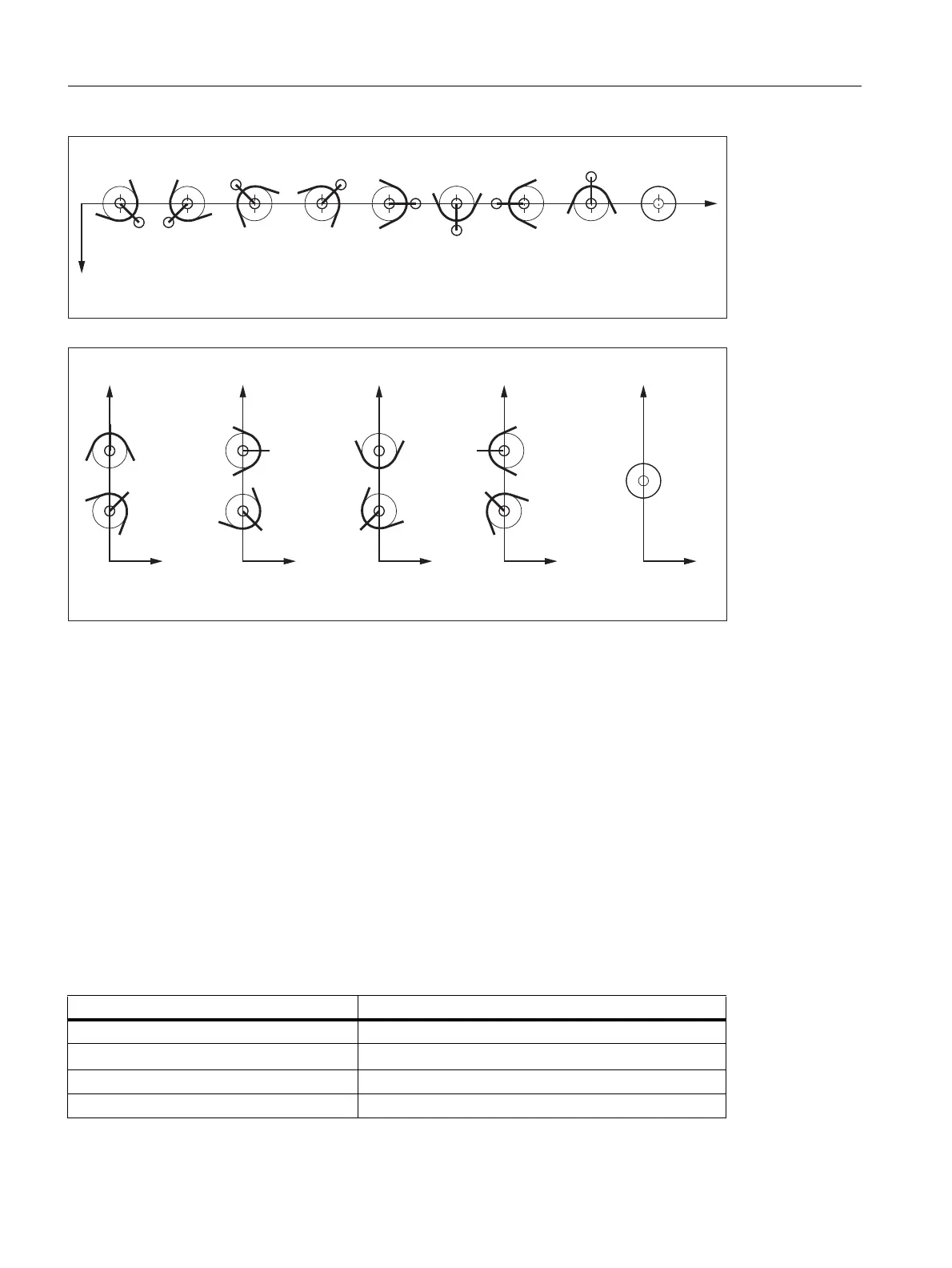
Figure 18-6 Tool parameter 2 (P2): Machining in front of the turning center
Figure 18-7 Tool parameter 2 (P2): Cutting edge position for vertical boring and turning mills
Special points to be noted
• If the cutting edge center point S is used instead of point P as a reference point to calculate the tool length
compensation, the identifier 9 must be entered for the cutting edge position.
• The identifier 0 (zero) is not permitted as a cutting edge position.
18.4.4 Tool parameters 3 - 5: Geometry - tool lengths
Description
The lengths of the tools are required for the geometry tool length compensation. They are input as tool lengths 1
to 3 in the tool parameters 3 to 5. The following length specifications must be entered as a minimum for each tool
type:
Tool type Required tool lengths
Tool type 12x, 140, 145, 150: Tool length 1
Tool type 13x: Tool length 1 to 3 (depending on plane G17-G19)
Tool type 2xx: Tool length 1
Tool type 5xx: Tool length 1 to 3
3 3 3 3 3 3 3
3 6
3 3
;
=
3
6
;
=
3 3
3
3 3
3 3
3 6
3
3
3
6
;
=
;
=
;
=
;
=

 Loading...


