P3: Basic PLC Program for SINUMERIK 840D sl
13.13 Block descriptions
Basic Functions
1058 Function Manual, 09/2011, 6FC5397-0BP40-2BA0
Description of formal parameters
The table below shows all formal parameters of the "MCP_IFM2" function:
Call example
With these parameter settings, the signals are sent to the 1st mode group, the 1st channel and all axes. In
addition, the spindle override is transferred in the 4th axis/spindle interface. The feed hold signal is passed to bit
memory 22.0 and the spindle stop signal to data block DB2, data bit 151.0. The spindle direction feedback signal
supplied via parameter "SpindleDir" can be used as a direction input for an additional FC 18 call.
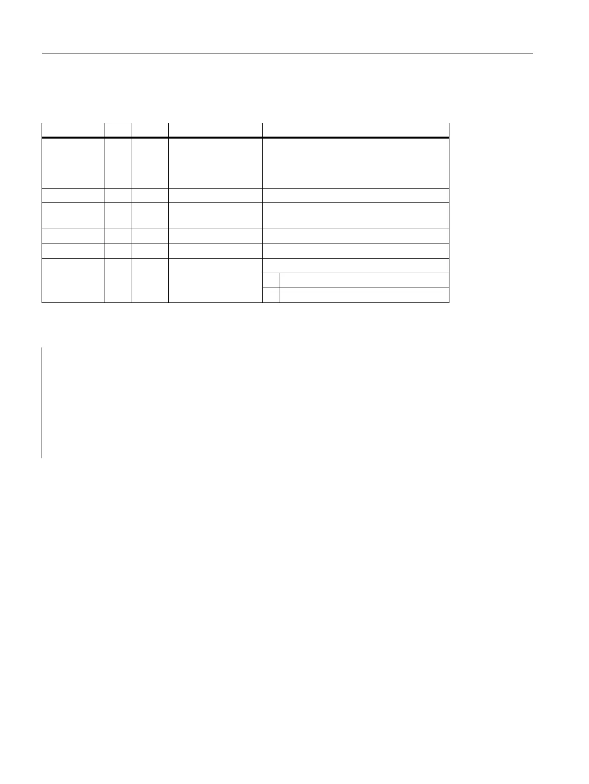
Signal Type Type Range of values Remark
BAGNo I BYTE 0 - b#16#0A
and
b#16#10 - b#16#1A
No. of mode group to which the mode signals
are transferred.
BAGNo >= b#16#10 means access to the
second machine control panel.
ChanNo I BYTE 0 - B#16#0A Channel no. for the channel signals
SpindleIFNo I BYTE 0 - 31
(B#16#1F)
Number of the axis interface declared as a
spindle
FeedHold A BOOL Feed stop from MCP, modal
SpindleHold A BOOL Spindle stop from MCP, modal
SpindleDir A BOOL Direction of spindle rotation
0: corresponds to + (left)
1: corresponds to - (right)
CALL FC 24 ( //Slim machine control panel M variants
//signals to interface
BAGNo := B#16#1, //Mode group no. 1
ChanNo := B#16#1, //Channel no. 1
SpindleIFNo := B#16#4, //Spindle interface number = 4
FeedHold := m22.0, //Feed stop signal modal
SpindleHold := db2.dbx151.0); //Spindle stop modal in message data block
SpindleDir:= m22.1); //Spindle direction return

 Loading...


