A3: Axis Monitoring, Protection Zones
2.3 Protection zones
Basic Functions
Function Manual, 09/2011, 6FC5397-0BP40-2BA0
113
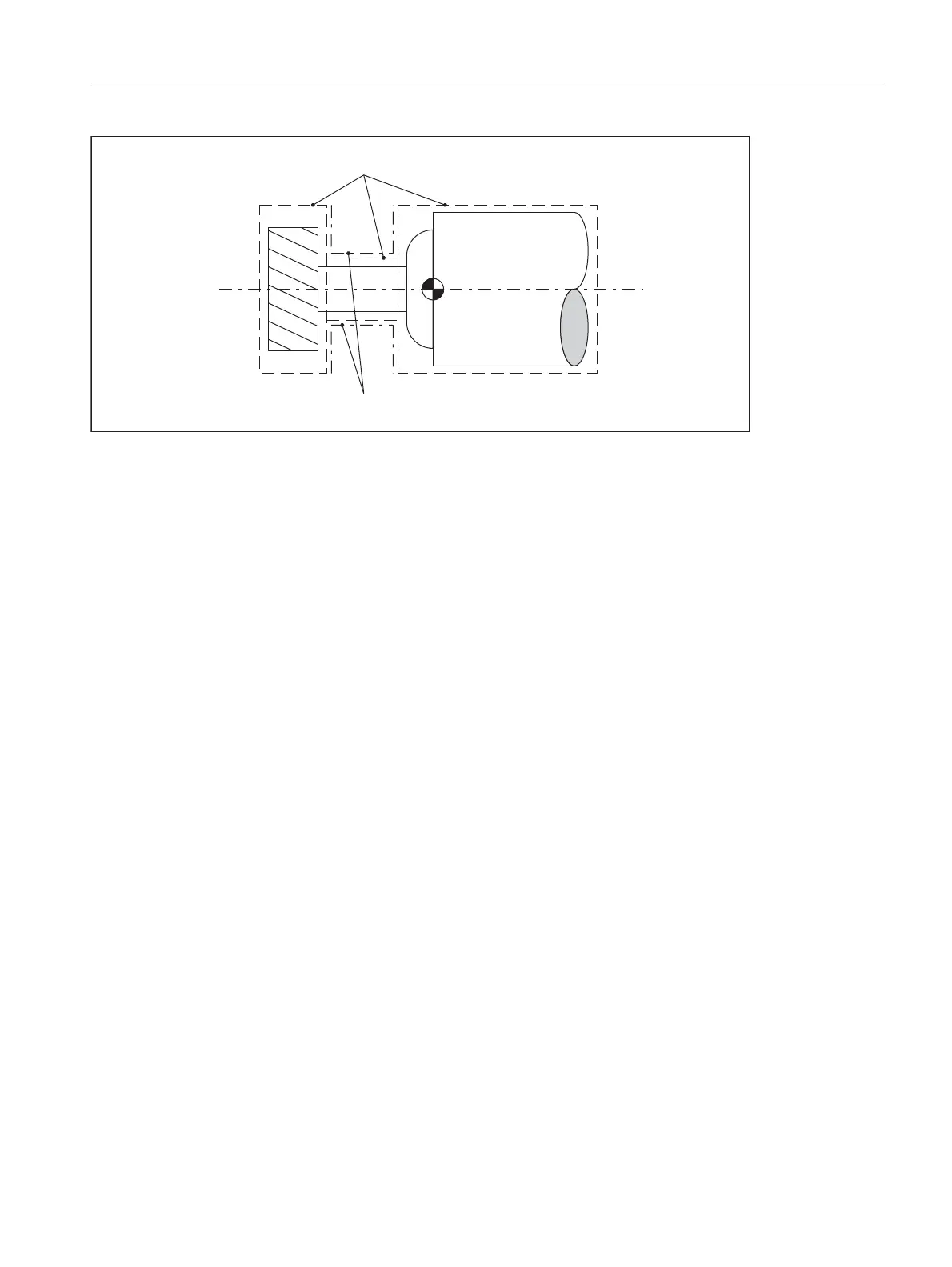
Figure 2-12 Examples: convex and concave tool-related protection zones
Contour elements
The following contour elements are permissible:
• G0, G1 for straight contour elements
• G2 for circle segments in the clockwise direction
Permissible only for workpiece-related protection zones.
Not permissible for tool-related protection zones because they must be convex.
• G3 for circular segments in the counterclockwise direction
A protection zone cannot be described by a complete circle. A complete circle must be divided into two half
circles.
The sequence G2, G3 or G3, G2 is not permitted. A short G1 block must be inserted between the two circular
blocks.
Constraints
During the definition of a protection zone, the following functions must not be active or used:
• Tool radius compensation (cutter radius compensation, tool nose radius compensation)
• Transformation
• Reference point approach (G74)
• Fixed point approach (G75)
• Dwell time (G4)
• Block search stop (STOPRE)
• End of program (M17, M30)
• M functions: M0, M1, M2
Programmable frames (TRANS, ROT, SCALE, MIRROR) and configurable frames (G54 to G57) are ineffective.
Inch/metric switchovers with G70/G71 or G700/G710 are effective.
)
&RQFDYHSURWHFWLRQ]RQHVQRWSHUPLVVLEOH
&RQYH[SURWHFWLRQ]RQHV

 Loading...


