W1: Tool offset
18.4 Tool cutting edge
Basic Functions
Function Manual, 09/2011, 6FC5397-0BP40-2BA0
1455
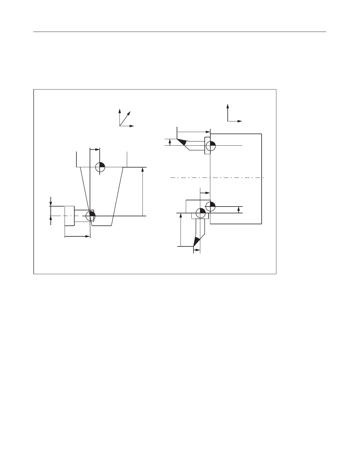
• The tool and the tool adapter are measured separately but are installed on the machine in one unit (the tool
size and adapter size are entered separately in a cutting edge).
• The tool is used in a second tool fixture located in another position (e.g. vertical and horizontal spindle).
• The tool fixtures of a tool turret are located at different positions.
Figure 18-8 Application examples for base-dimension/adapter-dimension TLC
Tool basic length 1 to 3 (tool parameters 21 to 23)
In order that the discrepancy between the toolholder reference point F and the toolholder reference point F' can
be corrected on the three geometry axes (three dimensional), all 3 basic lengths are active irrespective of the tool
type. In other words, a twist drill (tool type 200) with a tool length compensation (length 1) can also have a tool
base dimension/adapter dimension in 3 axes.
References
Please refer to the following documentation for more information about base-dimension/adapter-dimension tool
length compensation:
• Programming Manual, Fundamentals
/HQJWK
/HQJWK
7XUQLQJFHQWHU
/HQJWK
/HQJWK
)7RROKROGHUUHIHUHQFHSRLQWV
)7RROKROGHUUHIHUHQFHSRLQWV
7RROEDVH
GLPHQVLRQ
OHQJWK
7RROEDVH
GLPHQVLRQ
OHQJWK
/HQJWK
5DGLXV
0LOOLQJPDFKLQH 7XUQLQJPDFKLQH
7RROEDVH
GLPHQVLRQ
OHQJWK
7RROEDVH
GLPHQVLRQ
OHQJWK
;
=
<
)
=
;
)
)
)
)

 Loading...


