W1: Tool offset
18.6 Toolholder with orientation capability
Basic Functions
1498 Function Manual, 09/2011, 6FC5397-0BP40-2BA0
Description of the kinematics of the toolholder
The kinematics of the toolholder with orientation capability is described with a total of 33 parameter sets.
The data of the data block can be edited by the user.
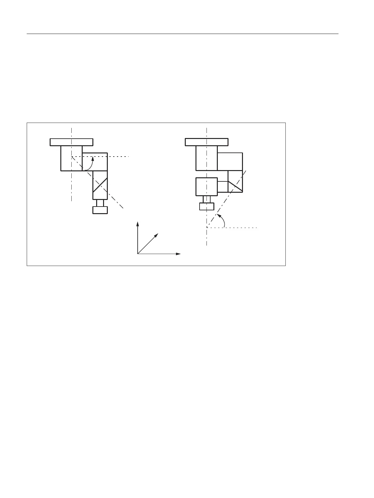
Toolholder with orientation capability
Example: Cardan toolholder with two axes for the tool orientation
Figure 18-38 Cardan toolholder with two axes
Processing toolholder data blocks
Two options are available:
• Explicit entry in the toolholder data block from the part program
• Automatic acceptance of certain values (angles) from a frame
A requirement for this is that TCOFR (Tool Carrier Orientation FRame) is also specified when the toolholder is
selected.
The tool orientation used to calculate the tool length is determined again from the frame active at this time
when a toolholder is changed.
9DULDQW 9DULDQW
˳
˳
$
&
\
]
$
&
[

 Loading...


