W1: Tool offset
18.6 Toolholder with orientation capability
Basic Functions
Function Manual, 09/2011, 6FC5397-0BP40-2BA0
1507
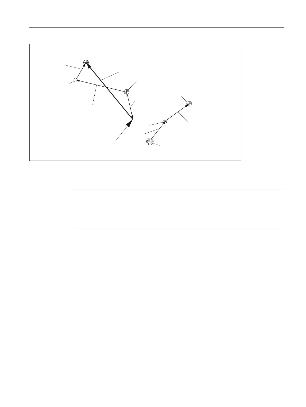
Figure 18-41 Kinematic sequence with extended kinematics
The following kinematic type is defined for machines with a rotary tool and rotary workpiece:
$TC_CARR23 using letter M (extended kinematics)
Rotary tool types T and M
For machine kinematics with a rotary tool (types T and M), the toolholder component with orientation capability,
which describes the tool or head component (as opposed to the table component), acts, in conjunction with the
active tool, as a new overall tool.
Fine offset
The offset vectors l
1
to l
4
and the offsets of the rotary axes v
1
and v
2
can be represented as the sum of a basic
value and a fine offset. The fine offset parameters assigned to the basic values are achieved by adding a value of
40 to the index of the basic value.
Note
On machines with extended kinematics it is generally useful, as with machines where only
the table can be rotated, for the machine reference point and the reference point of the table
to be identical. The (open) chain component to describe the table (see figure) is then closed.
In this special case, the following formula applies: l
3
= - l
4
7RROOHQJWK
ZHDU
WRROEDVHGLPHQVLRQ
5HVXOWLQJWRROOHQJWKFRPSHQVDWLRQ
5HIHUHQFHSRLQWRIWKHWRROKROGHU
7RRORULHQWDWLRQ
5HIHUHQFHSRLQWRIWKHWRRO
0DFKLQHUHIHUHQFHSRLQW
5HIHUHQFHSRLQWRIWKHWRROWDEOH
O
O
Y
˞
O
O
Y
˞

 Loading...


