W1: Tool offset
18.7 Cutting data modification for tools that can be rotated
Basic Functions
Function Manual, 09/2011, 6FC5397-0BP40-2BA0
1529
Cutting edge reference point
The cutting edge center point and the cutting edge reference point are defined for turning tools. The position of
these two points relative to each other is defined by the cutting edge position.
The distance of the two points for cutting edge positions 1 to 4 is equal to √ 2 times the cutting edge radius; for
cutting edge positions 5 to 8 it is equal to 1 times the cutting edge radius. In the first case, the cutting edge
reference point relative to the cutting edge center point lies in the machining plane on a bisecting line, while in the
second case it lies on a coordinate axis.
If your rotate the tool by a random angle around an axis vertical to the machining plane, the the cutting edge
reference point would also rotate if it had a fixed position relative to the tool. The above-mentioned condition
(position on an axis or a bisecting axis) is not fulfilled in most cases. This is not desirable. Instead, the cutting
edge reference point should always be modified in such a way that the distance vector between cutting edge
reference point and cutting edge center point has one of the mentioned 8 directions. The cutting edge position
must be modified for this if necessary.
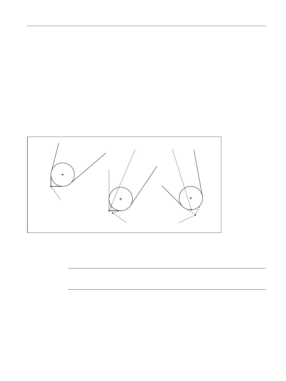
The ratios are shown with examples in the figure below:
Figure 18-46 Cutting edge reference point and cutting edge position (SL) for tool rotation
A tool with the cutting edge position 3, the clearance angle 22.5° and holder angle 112.5° is rotated. For rotations
up to 22.5°, the cutting edge position is maintained, the position of the cutting edge reference point relative to the
tool however, is compensated in such a way that the relative position of both points are maintained in the
machining plane. For bigger rotations (up to 67.5°), the cutting edge position changes to value 8.
Note
As the cutting edge reference point is defined by the tool length vector, modifying the cutting
edge reference point changes the effective tool length.
ROGFXWWLQJUHIHUHQFHSRLQW
6/
6/
6/
QHZFXWWLQJHGJHUHIHUHQFHSRLQW
FXWWLQJHGJHUHIHUHQFHSRLQW

 Loading...


