D1: Diagnostics tools
5.3 Service overview
Basic Functions
274 Function Manual, 09/2011, 6FC5397-0BP40-2BA0
Control technology concept
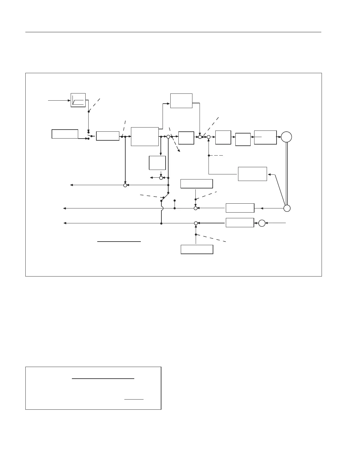
The figure below shows at which points in the controlloop the axis and spindle information is read off.
Figure 5-1 Overview diagram of axis and spindle information
Check of the position controller setting
The position controller settings can be easily monitored via the service display "axis/spindle". The number 1
(corresponds to servo gain=1) should be entered in machine data:
MD32200 $MA_POSCTRL_GAIN [n] (servo gain factor)
The change takes effect immediately.
For a feedrate of 1 m/mm, a following error of 1 mm must be obtained (for servo gain factor=1 and constant
velocity travel), as the servo gain factor is defined as follows:
If the desired servo gain factor (Kv) does not correspond to the actual factor, the possible causes and remedial
optimization options are as follows.
0
3RVLWLRQ
FRQWURO
OHU
6SLQGOHVSHHGVHWSRLQW
FXUUHQW
(UURUVLJQDO
3RVLWLRQVHWSRLQW
VSHHGVHWSRLQW
6SLQGOH
VSHHG
VHWSRLQW
SURJ
$EVFRPSHQVDWLRQYDOXH
0HDVXULQJV\VWHP
6SHHGVHWSRLQW>@
*
*
$FWXDOVSHHGYDOXH>@
&RQWURO
SDUDPHWHUVHW
&RQWRXU
GHYLDWLRQ
)ROORZLQJHUURU
HJIURP
GLUHFW
PHDVXULQJ
V\VWHP
$EVFRPSHQVDWLRQYDOXH
0HDVXULQJV\VWHP
$FWXDOSRVLWLRQYDOXHRIPHDVXULQJV\VWHP
$FWXDOSRVLWLRQYDOXHRIPHDVXULQJV\VWHP
$FWLYH
PHDVXULQJ
V\VWHP
6HUYRJDLQIDFWRUFDOFXODWHG
6SHHGVHWSRLQW
)ROORZLQJHUURU
9DOXHLVGLVSOD\HGLQXVHULQWHUIDFH
,WDOLFIRQW
)LQH
LQWHUSRODWRU
-HUNOLPLWDWLRQ
'\QDPLF
UHVSRQVH
DGDSWDWLRQ
)HHG
IRUZDUG
FRQWURO
&RQWURO
ORRS
PRGHO
6SHHG
FRQW
UROOHU
&XUUHQW
FRQWURO
OHU
3RZHU
VHFWLRQ
$FWXDOVSHHG
YDOXH
VSHFLILFDWLRQ
&RPSHQVDWLRQ
%DFNODVK/(&
$FWXDOYDOXH
SURFHVVLQJ
$FWXDOYDOXH
SURFHVVLQJ
&RPSHQVDWLRQ
%DFNODVK/(&
,QWHUSRODWRU
,32
ฬ
.
Y
IDFWRU
9HORFLW\VHWSRLQW
)ROORZLQJHUURU
8QLWIRUWKHVWDQGDUGVHWWLQJ
>PPLQ@
>PP@

 Loading...


