K2: Axis Types, Coordinate Systems, Frames
10.5 Frames
Basic Functions
Function Manual, 09/2011, 6FC5397-0BP40-2BA0
783
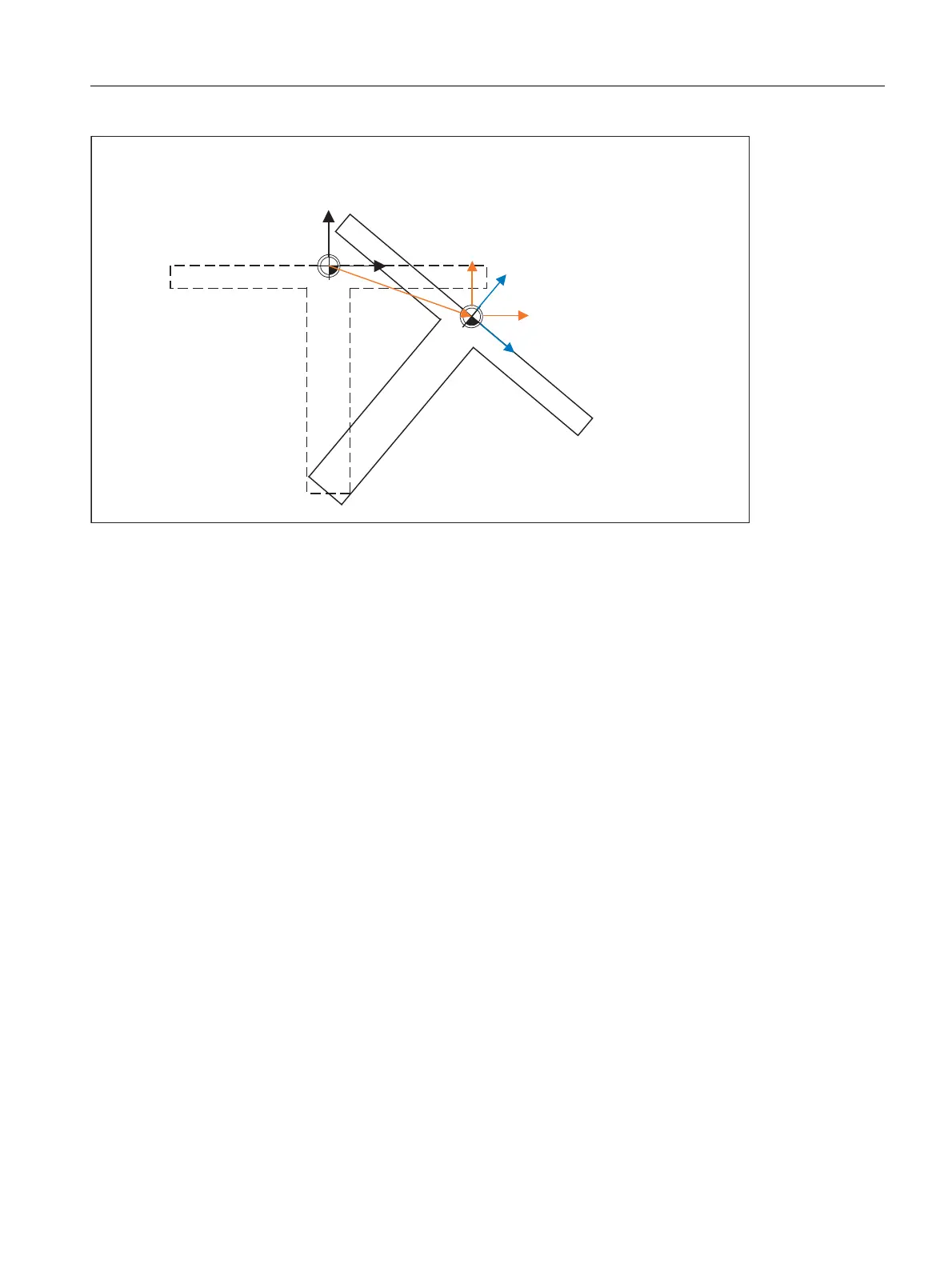
Figure 10-23 Frame on activation of a rotary table with TCARR
With kinematics of type M (tool and table are each rotary around one axis), the activation of a toolholder with
TCARR simultaneously produces a corresponding change in the effective tool length (if a tool is active) and the
zero offset.
Rotations
Depending on the machining task, it is necessary to take into account not only a zero offset (whether as frame or
as tool length) when using a rotary toolholder or table, but also a rotation. However, the activation of an
orientational toolholder never leads directly to a rotation of the coordinate system.
If only the tool can be rotated, a frame can be defined for it using TOFRAME or TOROT.
With rotary tables (kinematics types P and M), activation with TCARR similarly does not lead to an immediate
rotation of the coordinate system, i.e. even though the zero point of the coordinate system is offset relative to the
machine, while remaining fixed relative to the zero point of the workpiece, the orientation remains unchanged in
space.
If the coordinate system needs to be fixed relative to the workpiece, i.e. not only offset relative to the original
position but also rotated according to the rotation of the table, then PAROT can be used to activate such a rotation
in a similar manner to the situation with a rotary tool.
With PAROT, the translations, scalings and mirroring in the active frame are retained, but the rotation component
is rotated by the rotation component of an orientational toolholder corresponding to the table.
Up to and including SW P6.1, the rotation activated by PAROT is calculated in the programmable frame
($P_PFRAME), thus changing its rotation component.
With SW P6.2 and higher, the entire programmable frame remains unchanged, including its rotation component.
The rotation component, which describes the rotation of the tool table, is then entered into system frame
$PARTFR, if bit 2 of machine data
MD28082 $MC_MM_SYSTEM_FRAME_MASK
is set.
Alternatively, the basic frame described in machine data
2ULJLQDOSRVLWLRQRIWKH
FRRUGLQDWHV\VWHP
2ULJLQDOSRVLWLRQRIWDEOH
3RVLWLRQRIWDEOH
DIWHUURWDWLRQ
3RVLWLRQRIFRRUGLQDWHV\VWHP
DIWHU7&$55
3RVLWLRQRIFRRUGLQDWHV\VWHP
DIWHU3$527

 Loading...


