P3: Basic PLC Program for SINUMERIK 840D sl
13.7 Interface structure
Basic Functions
Function Manual, 09/2011, 6FC5397-0BP40-2BA0
867
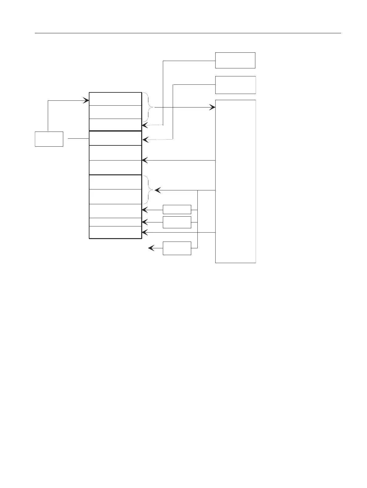
Figure 13-7 PLC/NCK channel interface
PLC/axis, spindle, drive signals
The axis-specific and spindle-specific signals are divided into the following groups:
• Shared axis/spindle signals
• Axis signals
• Spindle signals
• Drive signals
The signals are transmitted cyclically at the start of OB 1 with the following exceptions:
Exceptions include:
• Axial F value
•M value
•S value
An axial F value is entered via the M, S, F distributor of the basic program if it is transferred to the PLC during the
NC machining process.
The M and S value are also entered via the M, S, F distributor of the basic program if one or both values require
processing.
3URJUDPFRQWURO
7UDYHUVHVLJQDOV
*(2D[HV
%\WHV
3URJUDPFRQWURO
IURP+0,
3URJUDPFKDQQHO
VWDWXV
*HRD[HVVWDWXV
067''/+)
YDOXHV
'HFRGHG0VLJQDOV
00
$FWLYH*IXQFWLRQV
'%
0GHFRGHU
0&3
+0,
1&FKDQQHO
*JURXS
GHFRGHU
06)
GLVWULEXWRU
$[LVVSLQGOH
LQWHUIDFH
&RQWUROVLJQDOV
6WDWXVVLJQDOV
$X[LOLDU\*IXQFWLRQV
%3
%3
$FWLYDWLQJSURWHFWLRQ
]RQHV
6WDWXVVLJQDOV
3URWHFWLRQ]RQHV
$X[LOLDU\IXQFWLRQ
FKDQJHVLJQDOV
+0,VLJQDO
URXWLQJ

 Loading...


