P3: Basic PLC Program for SINUMERIK 840D sl
13.8 Structure and functions of the basic program
Basic Functions
900 Function Manual, 09/2011, 6FC5397-0BP40-2BA0
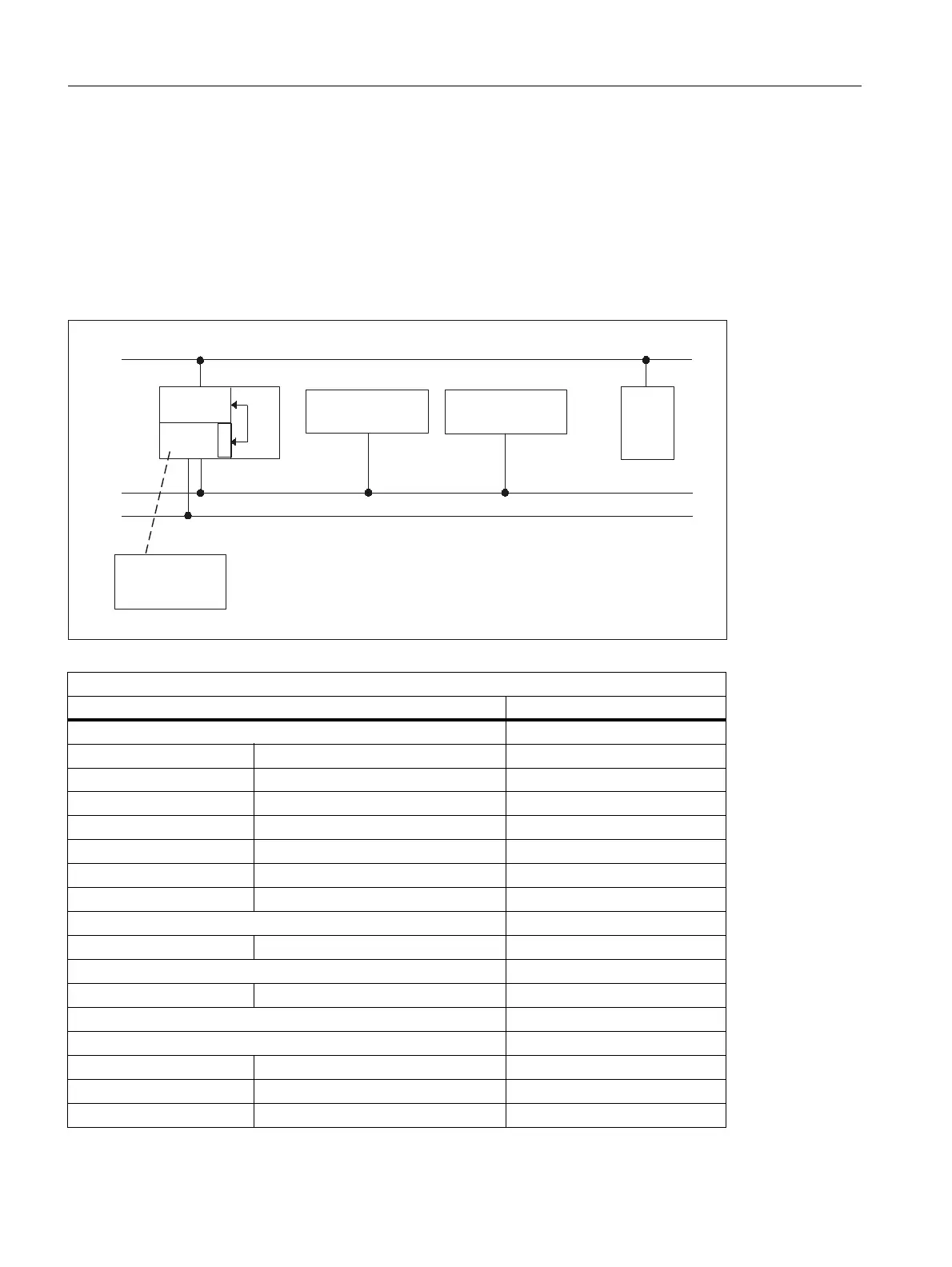
840Dsl: PROFIBUS connection on the MPI/DP port
With the PROFIBUS connection of the MCP, this component must be considered in the STEP 7 hardware
configuration. The MCP is connected on the MPI/DP bus of the PLC.
The addresses must be stored in the input and output log range. These start addresses must also be stored in
the pointer parameters of the FB1. The FB1 parameters listed below are used for further parameter assignment.
There is no PROFIBUS variant of the HHU. For this reason, an Ethernet connection is shown for the HHU in this
diagram. The PROFIBUS slave address must be stored in the MCP1BusAdr and MCP2BusAdr. Enter the pointer
to the configured diagnostic address (e.g. P#A8190.0) in MCPxStatRec.
Figure 13-18 840Dsl: PROFIBUS connection on the MPI/DP port
Relevant parameters (FB1)
MCP HHU
MCPNum = 1 or 2 (number of MCPs) HHU = 5 (via CP 840Dsl)
MCP1In MCP2In BHGIn
MCP1Out MCP2Out BHGOut
MCP1StatSend (n.r.) MCP2StatSend (n.r.) BHGStatSend
MCP1StatRec MCP2StatRec BHGStatRec
MCP1BusAdr MCP2BusAdr BHGInLen
MCP1Timeout MCP2Timeout BHGOutLen
MCP1Cycl (n.r.) MCP2Cycl BHGTimeout (n.r.)
MCPMPI = FALSE BHGCycl (n.r.)
MCP1Stop MCP2Stop BHGRecGDNo
MCPBusType = b#16#44 BHGRecGBZNo (n.r.)
BHGRecObjNo (n.r.)
MCPSDB210= FALSE BHGSendGDNo (n.r.)
MCPCopyDB77 = FALSE BHGSendGBZNo (n.r.)
BHGSendObjNo (n.r.)
BHGMPI = FALSE
BHGStop
03,'3
'3
++8
1&.
(WKHUQHW
0&3
0&3
'
3
5
352),%86
FRQILJIRU0&3
&3
'VO
LQW3/&

 Loading...


