*) If the outputs for the illuminated pushbuttons (X53/X54) are loaded with the max. permissible current
of 0.3 A, this results in additional power consumption of 36 W. The total power consumption is then 50
W.
See also
Other values/standards: Application planning (Page 35)
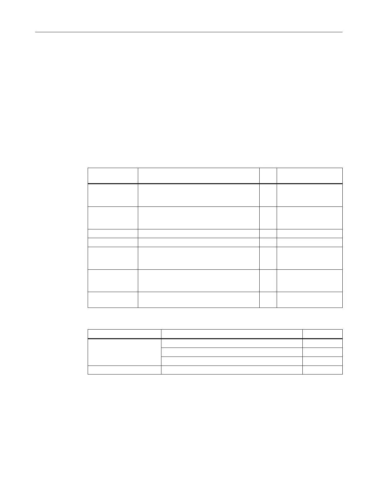
7.3.6 Spare parts and accessories
Table 7-16 Spare part kits for machine control panel MCP 483C PN
Name Description Qua
ntity
Article number
Emergency Stop
button
22 mm actuating element, 40 mm mushroom
pushbutton, snap action with tamper protection,
latching, red, with holder, non-illuminated
1 3SB3000-1HA20
Contact block with 2 contact pairs (1 NO + 1 NC), 2-pin, screw
terminal (3rd contact pair can be additionally
connected)
1 3SB3400-0A
Set of keys Set of keys for machine control panel 10 6FC5148–0AA03–0AA0
Rapid traverse dial for 16-stage rotary switch 20 6FC5248–0AF30–0AA0
Rotary switch for
spindle
Spindle/rapid traverse override, electronic rota‐
ry switch 1x16G, T=24, cap, knob, pointer, spin‐
dle and rapid-traverse dials
1 6FC5247–0AF12–1AA0
Rotary switch for
feed
Override feedrate / rapid traverse electronic ro‐
tary switch 1x23G, T=32, cap, knob, pointer,
feedrate and rapid-traverse dials
1 6FC5247–0AF13–1AA0
Set of tensioners Set of tensioners for supplementary operator
components with 2.5 mm profile, 20mm length
9 6FC5248–0AF14–0AA0
Table 7-17 Accessories pack (for delivery ex works)
Component Description Amount
Keyset Key caps for turning (labeled) 9
Ergo gray key caps (can be labeled) 30
Clear key caps (can be labeled) 30
Yellow backing plate for emergency stop 1
Anschließbare Komponenten
7.3 MCP 483C PN
PPU and components
Manual, 05/2015, 6FC5397-2DP40-3BA4 135

 Loading...


