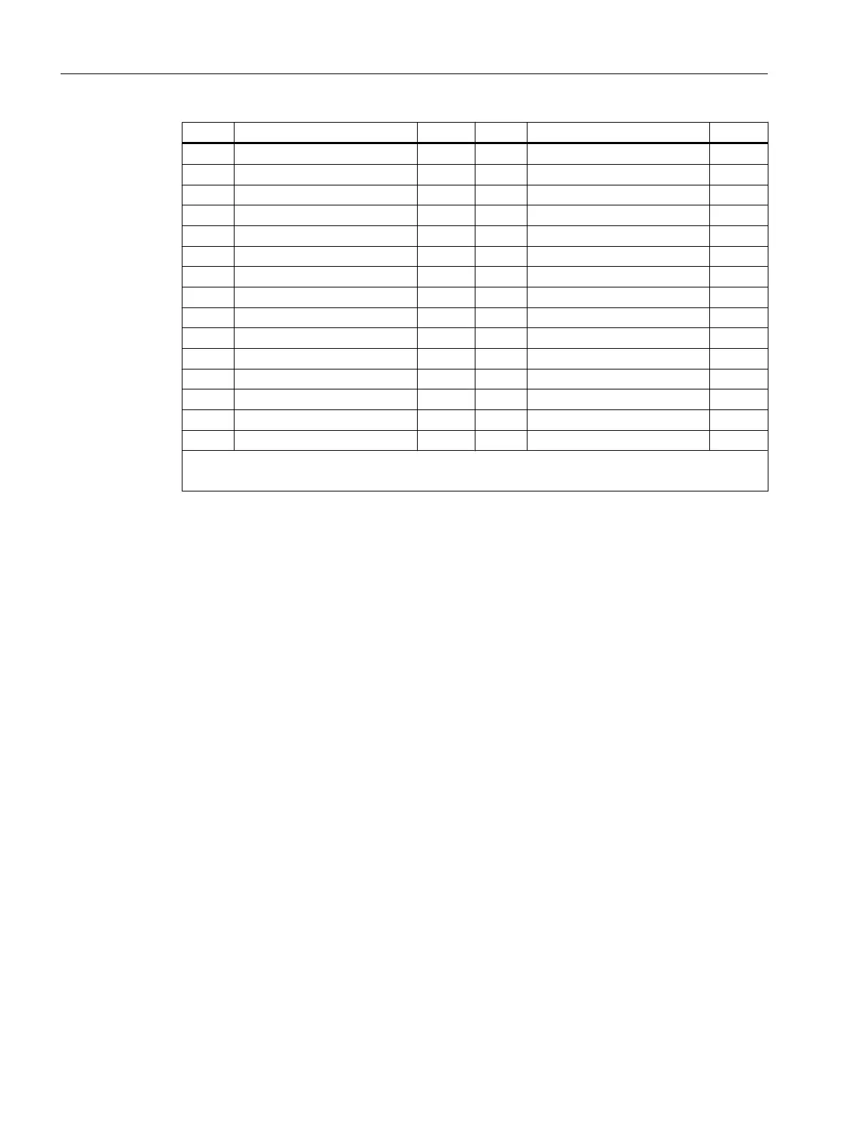
Pin Signal name Type Pin Signal name Type
21 DI 8.2 I 22 DI 8.3 I
23 DI 8.4 I 24 DI 8.5 I
25 DI 8.6 I 26 DI 8.7 I
27 Not assigned - 28 Not assigned -
29 Not assigned - 30 Not assigned -
31 DO 4.0 O 32 DO 4.1 O
33 DO 4.2 O 34 DO 4.3 O
35 DO 4.4 O 36 DO 4.5 O
37 DO 4.6 O 38 DO 4.7 O
39 DO 5.0 O 40 DO 5.1 O
41 DO 5.2 O 42 DO 5.3 O
43 DO 5.4 O 44 DO 5.5 O
45 DO 5.6 O 46 DO 5.7 O
47 DOCOM3 VI 48 DOCOM3 VI
49 DOCOM3 VI 50 DOCOM3 VI
VI: Voltage input/VO: Voltage Output
I: Signal input/O: Signal output/GND: Reference potential (ground)
Cable specification:
● 50-pin ribbon cable connector: 50-pin insulation piercing connecting device with strain relief,
ribbon cables and terminal converter are required to connect the digital inputs and outputs.
● The required connecting cables (ribbon cables) must be provided by the user. Maximum
cable length: 30 m
7.8.3.4 Specification of the digital inputs
Terminal assignment for the digital inputs
Features:
● X222: DI 3.0 to 3.7 are connected as rapid inputs.
● The inputs have no signaling (status LEDs).
● The inputs are not isolated.
● It is not possible to connect a 2-wire BERO.
The following figure shows an example of the terminal assignment for the digital inputs on
connector X111. Connectors X222 and X333 are assigned analogously.
Anschließbare Komponenten
7.8 PP 72/48D PN
PPU and components
204 Manual, 05/2015, 6FC5397-2DP40-3BA4

 Loading...


