7.11 Activating and addressing components
7.11.1 Activating components
Machine data for the PLC I/O
The following components are assigned fixed addresses for the input and output image of the
PLC: I/O modules, machine control panel, SENTRON PAC and PN/PN coupler.
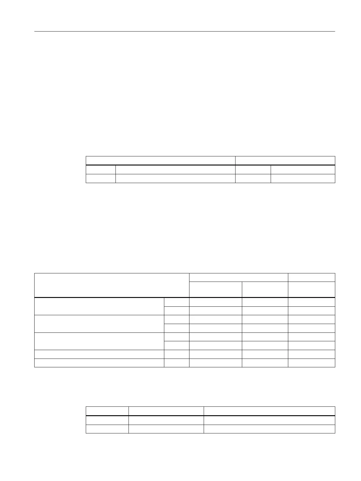
To deactivate the update of the input and output images of the PLC, set the following machine
data:
Machine data Value range
12986[i] $MN_PLC_DEACT_IMAGE_LADDR_IN 0 ≤ i ≤ 15 Input addresses
12987[i] $MN_PLC_DEACT_IMAGE_LADDR_OUT 0 ≤ i ≤ 15 Output addresses
The SINUMERIK 828D works with a fixed maximum configuration of the I/O modules. As
delivered, the data transfer to the input and output image of the PLC is deactivated for all I/O
modules.
To activate a PN component, you must enter the value -1 ("empty") in MD12986[i], see the
table in Section Addressing components (Page 256). MD12987[i] is preset with the value -1
and must not be changed.
Machine control panel
To activate the machine control panel, check the setting of the following machine data:
Machine data MCP type PN MCP type USB
Addressing via im‐
age
Addressing via
DB1000
Addressing via
DB1000
MD12950 $MN_PLC_MCP_CONNECT [0] 0 0 1
[1] -1 -1 -1
MD12951 $MN_PLC_MCP_CONNECT [0] 112 112 112
[1] 0 0 0
MD12952 $MN_PLC_MCP_CONNECT [0] 112 112 112
[1] 0 0 0
MD12986 $MN_PLC_DEACT_IMAGE_LADDR_IN [6] -1 -1 112
MD19720 $MN_PLC_FUNCTION_MASK Bit 0 0 1 0
Example
In this example, two I/O modules and a machine control panel of the PN type are activated:
MD Logical input address Data transfer to the PLC deactivated
12986[0] -1 1st PP module active
12986[1] -1 2nd PP module active
Anschließbare Komponenten
7.11 Activating and addressing components
PPU and components
Manual, 05/2015, 6FC5397-2DP40-3BA4 255

 Loading...


