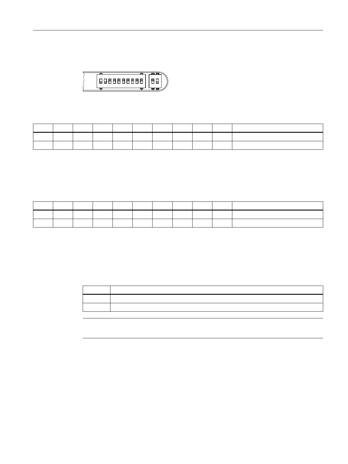
Switch S1, S2
Table 7-56 Setting of switch S1 as delivered
1 2 3 4 5 6 7 8 9 10 Meaning
ON ON PLC I/O Interface
OFF OFF OFF OFF OFF OFF OFF OFF PROFINET address "0"
The two switches S1-9 and S1-10 must remain set to "ON".
The switches S1-1 to S1-8 define the PROFINET address. For a SINUMERIK 828D, the address "64" must always be assigned
to the MCP.
Table 7-57 Switch S1 settings
1 2 3 4 5 6 7 8 9 10 Meaning
ON ON ON
OFF OFF OFF OFF OFF OFF OFF PROFINET address "64"
Further information on the addressing can be found in Section Addressing components
(Page 256).
The handwheel signal type is set with switch S2-1.
Table 7-58 Switch S2 settings
1 Meaning
ON differential interface
OFF TTL interface
Note
Switch S2-2 is reserved for test purposes.
7.5.3 Parameter assignment
The specifications for assigning input and output bytes listed in the tables are defined as
standard addresses in the PLC. Information on settings in the machine data can be found in
Section Activating components (Page 255).
Anschließbare Komponenten
7.5 MCP Interface PN
PPU and components
Manual, 05/2015, 6FC5397-2DP40-3BA4 169

 Loading...


