The internal power supply (P24OUT) is taken from the general power supply of module X1,
pin 2 (P24). Alternatively, an external power supply can be connected if the load at the digital
outputs becomes too high.
Technical data
Electrical specification of the digital inputs:
Digital inputs Min. Max. Nominal
High-level voltage (U
H
) 15 V 30 V 24 V
Input current I
IN
at V
H
2 mA 15 mA --
Low-level voltage (U
L
) -3 V +5 V 0 V
Signal delay time T
PHL
0.5 ms 3 ms --
Signal delay time T
PHL
for X222: DI 3.0 to 3.7 -- -- 600 μs
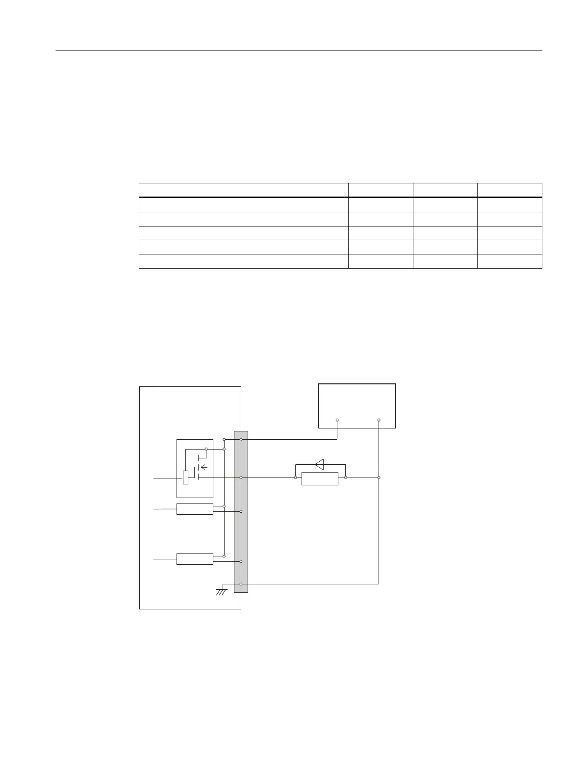
7.9.3.5 Specification of the digital outputs
Terminal assignment for the digital outputs
The following figure shows an example of the terminal assignment for the digital outputs on
connector X111. Connectors X222 and X333 are assigned analogously.
([WSRZHUVXSSO\
9'&VWDELOL]HG
;;;
3LQQXPEHU
'ULYHUV
'ULYHUV
'ULYHUV
5HOD\V
9
9
'2&20[
:
:
:
:
1 (M)
0
Figure 7-57 Terminal assignment for the digital outputs
Anschließbare Komponenten
7.9 PP 72/48D 2/2A PN
PPU and components
Manual, 05/2015, 6FC5397-2DP40-3BA4 227

 Loading...


