6.2 Power supply connection
6.2.1 Requirements for the power supply
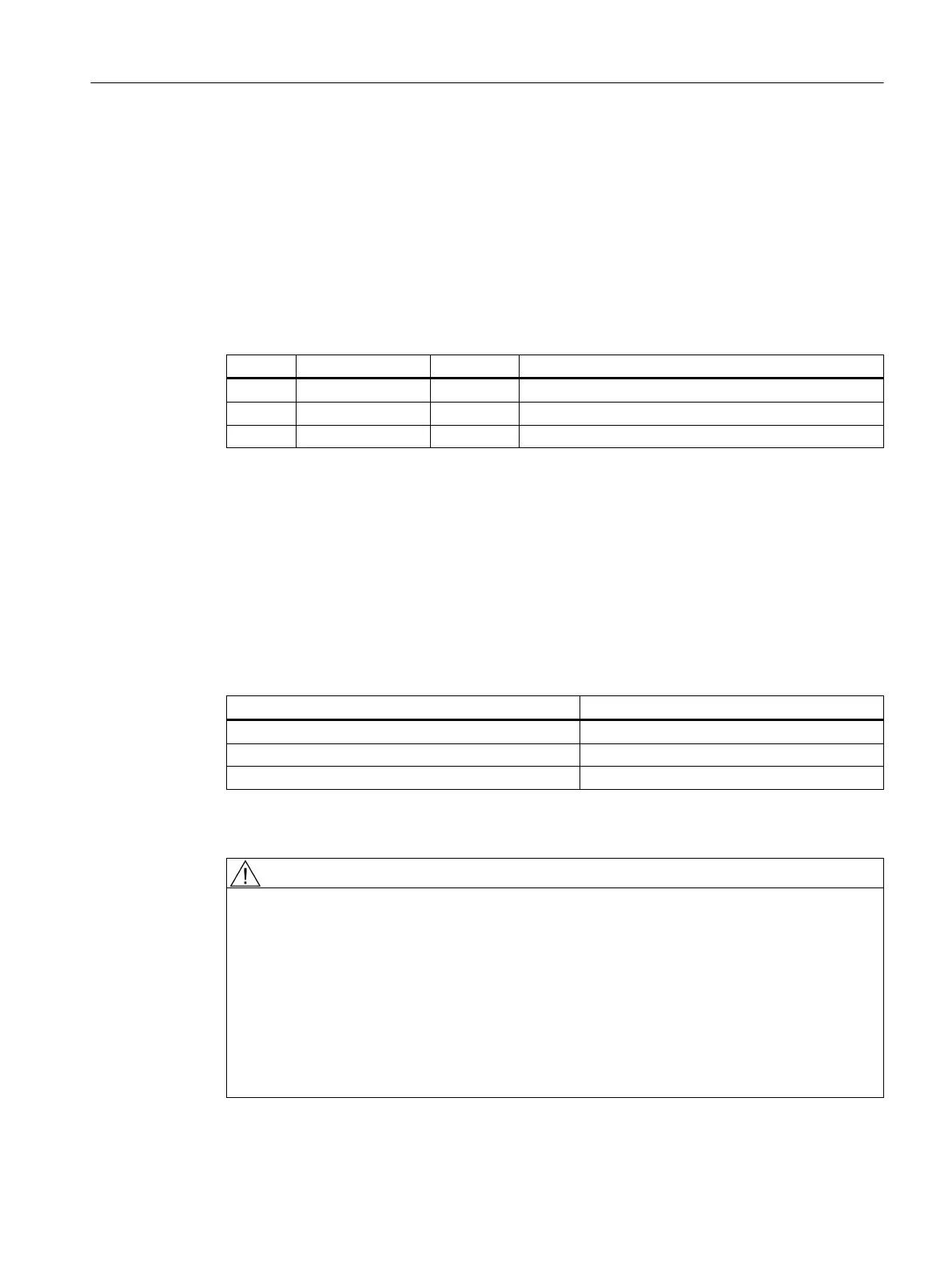
Pin assignment at X1 screw-type terminal block
Table 6-1 Pin assignment
Pin Signal name Signal type Meaning
1 P24 VI 24 VDC power supply
2 M VO Ground
3 PE GND Protective ground
Requirements of DC power supplies
Interface X1 is intended exclusively for the connection of the external 24 V power supply, e.g.
● SITOP (stabilized 24 V power supplies)
● CSM (Control Supply Module)
The following power consumption values for the PPU provide a configuration basis for
calculating the 24 VDC power supply.
Table 6-2 Input voltage specification
Parameter Values
Typ. power consumption
1)
1.2 A
Max. power consumption
2)
2.5 A
Max. starting current 4.4 A
1)
PPU only (processor, memory, etc.)
2)
PPU with full load (USB, handwheels)
DANGER
Risk of lightning strike
In the case of supply lines > 10 m, protectors must be installed at the device input in order to
protect against lightning (surge).
The DC power supply must be connected to the ground/shield of the control unit for EMC and/
or functional reasons. For EMC reasons, this connection should only be made at one point.
As a rule, the connection is provided as standard in the PLC I/Os. If this is not the case in
exceptional circumstances, the ground connection should be made on the grounding rail of
the control cabinet.
See also: "EMC Installation Guideline" Configuration Manual
Interface description
6.2 Power supply connection
PPU and components
Manual, 05/2015, 6FC5397-2DP40-3BA4 69

 Loading...


