7.1.1 Operator controls and displays
Operator controls (front)
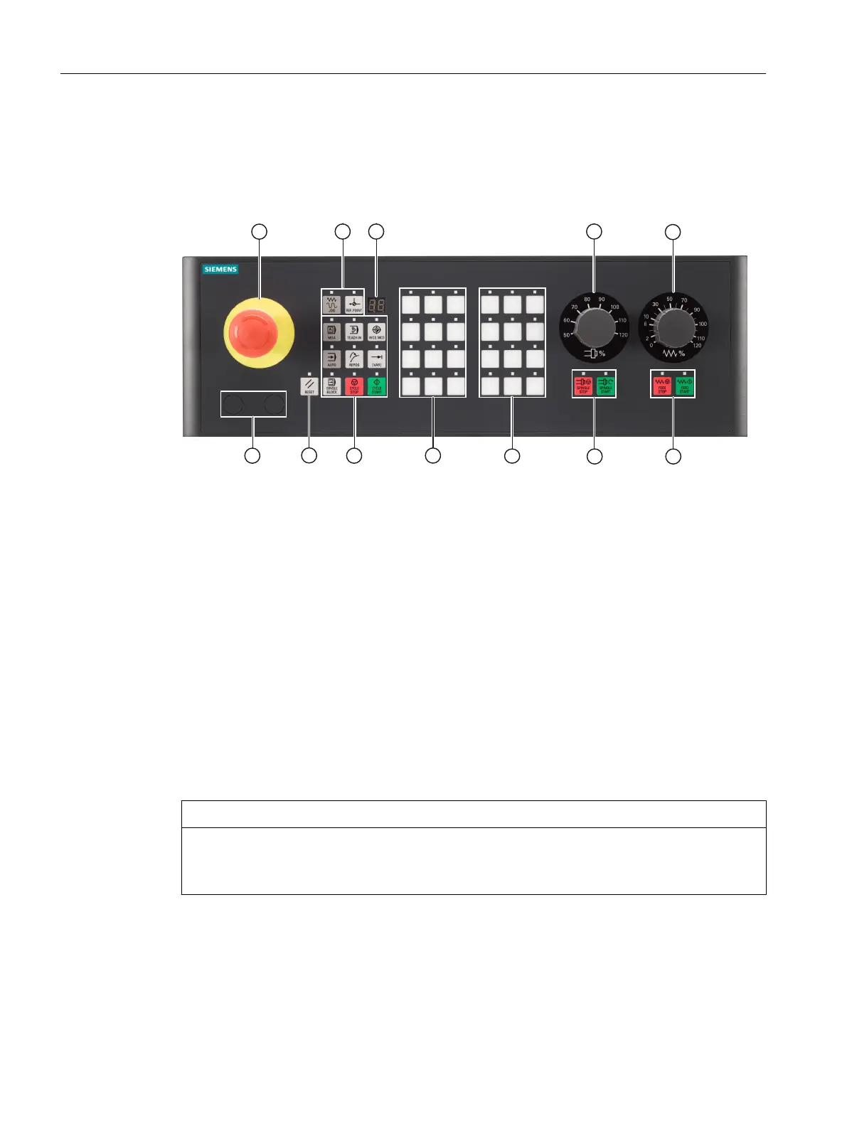
① Slot for the Emergency Stop button
② JOG and reference point keys
③ Display for the tool number
④ Slots for control devices (d = 16 mm, e.g. switch)
Drill mounting holes to install control devices.
⑤ Reset button
⑥ Keys for operating modes, machine functions and program control
⑦ Customer keys
⑧ Direction keys with rapid traverse override for lathes and milling machines
⑨ Override switch for the spindle
⑩ Override switch for the feed control
⑪ Keys for spindle control
⑫ Keys for feed control
Figure 7-1 Position of operator controls
NOTICE
Slots for control devices
Do not break out the openings for mounting control devices (risk of damage), rather drill them
to the required width.
Printed slide-in labels are included in the accessory pack for labeling key groups for operation
in milling machines and lathes. You can individually label the customer keys, see Section Spare
parts and accessories (Page 104). Blank slide-in labels are included in the accessory pack.
Anschließbare Komponenten
7.1 MCP 483 USB
PPU and components
94 Manual, 05/2015, 6FC5397-2DP40-3BA4

 Loading...


