MD Logical input address Data transfer to the PLC deactivated
12986[2] 18 3rd PP module inactive
12986[3] 27 4th PP module inactive
12986[4] 36 5th PP module inactive
12986[5] 96 PN/PN coupler inactive
12986[6] -1 Machine control panel of the PN type active
12986[8] 132 SENTRON PAC4200
12986[9] 144 SENTRON PAC3200
Note
Monitoring the I/O
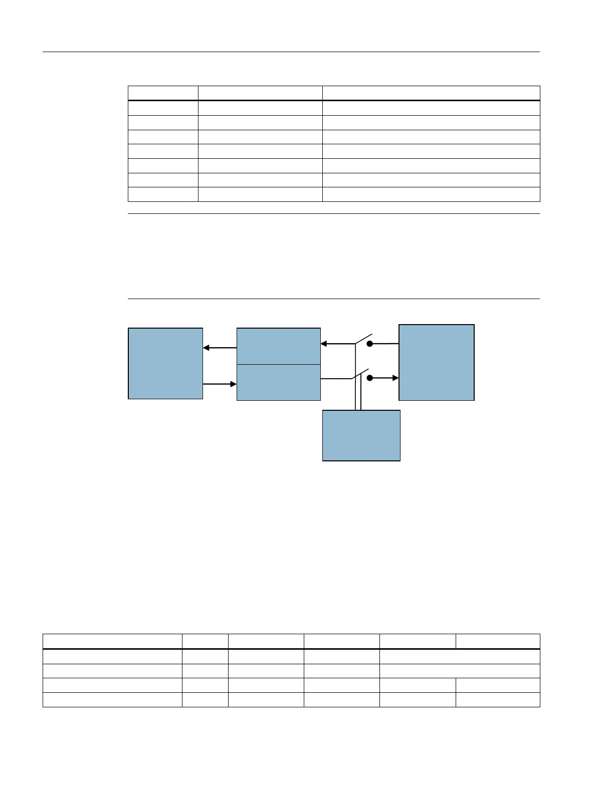
The use of an input/output address of a deactivated module in the PLC user program does not
trigger an alarm. The PLC user program always works with the image memory. Whether there
is a connection to the physical inputs/outputs is configured via MD12986[i] and MD12987[i].
Active modules are then monitored cyclically for failure.
31PRGXOH3/&XVHU
SURJUDP
,QSXWV
,%
2XWSXWV
4%
0'>L@
RU
0'>L@
Figure 7-64 I/O switch
7.11.2 Addressing components
IP addresses of the PN components
The following table contains the IP address of the respective PN component. It is set on the
PN component with a DIP switch. In this case, the maximum configuration with I/O modules,
bus coupler and machine control panel via the PLC I/O Interface based on PROFINET is taken
into consideration.
PN component Bus Device name IP address Input addresses Output addresses
192.168.214. (active with MD12986[x] = -1)
Index n:
1st PP module digital PN pp72x48pn9 9 0 … 8 0 … 5
2nd PP module digital PN pp72x48pn8 8 9 … 17 6 … 11
Anschließbare Komponenten
7.11 Activating and addressing components
PPU and components
256 Manual, 05/2015, 6FC5397-2DP40-3BA4

 Loading...


