7.3.1 Operator controls and display elements
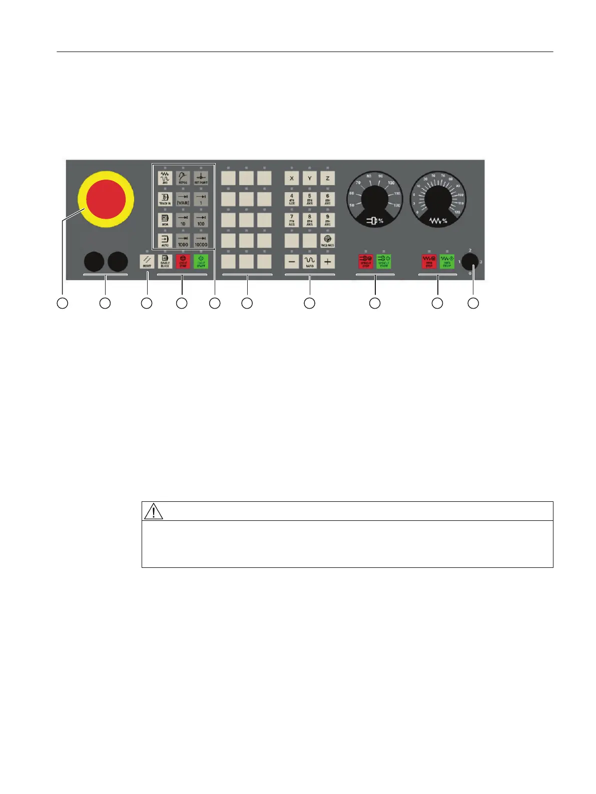
Operator controls (front)
① Emergency-Stop button
② Installation locations for control devices (d = 16 mm)
③ Reset button
④ Program control
⑤ Operating modes, machine functions
⑥ User keys T1 to T15
⑦ Direction keys with rapid traverse override (R1 to R15)
⑧ Spindle control with override switch
⑨ Feed control with override switch
⑩ Keyswitch (four positions)
Figure 7-11 Position of control elements on MCP 483C PN
WARNING
Mounting slots for control devices
The openings for installing control devices ② in "Position of control elements of MCP483C
PN" Fig. must not be broken out (risk of damage) but carefully drilled to the required width.
Anschließbare Komponenten
7.3 MCP 483C PN
PPU and components
Manual, 05/2015, 6FC5397-2DP40-3BA4 121

 Loading...


