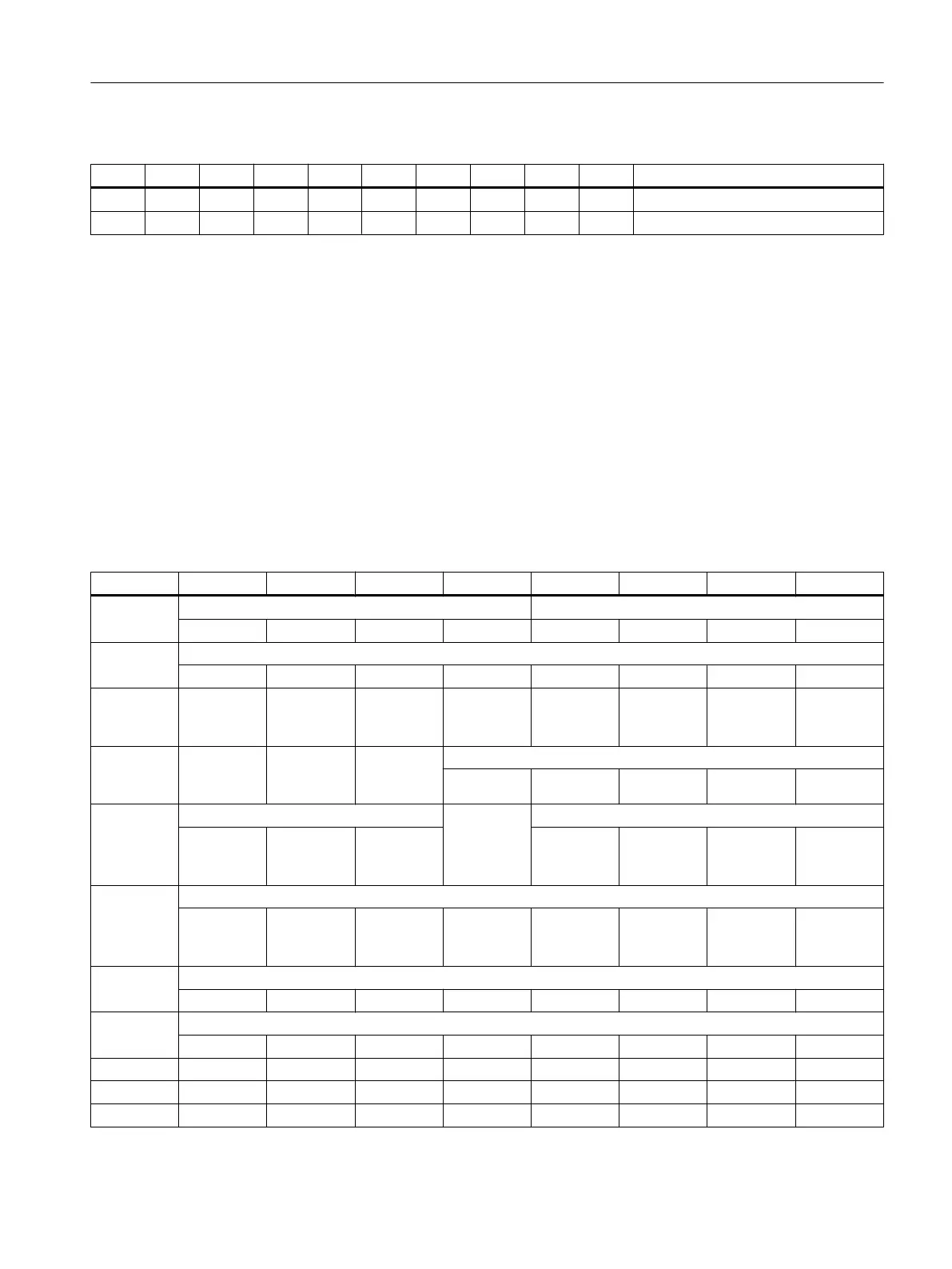
Table 7-12 Settings of switch S2
1 2 3 4 5 6 7 8 9 10 Meaning
ON ON ON
OFF OFF OFF OFF OFF OFF OFF PROFINET address "64"
Further information on the addressing can be found in Section Addressing components
(Page 256).
7.3.4 Parameterization
The specifications for assigning input and output bytes listed in the tables are defined as
standard addresses in the PLC. Information on settings in the machine data can be found in
Section Activating components (Page 255).
Standard input image
Table 7-13 Input image MCP 483C PN
Byte Bit7 Bit6 Bit5 Bit4 Bit3 Bit2 Bit1 Bit0
EB112 Spindle override Operating mode
D (2
3
) C (2
2
) B (2
1
) A (2
0
) JOG TEACH IN MDI AUTO
EB113 Machine function
REPOS REF. var. INC 10000 INC 1000 INC 100 INC 10 INC 1 INC
EB114 Keyswitch
position 0
Keyswitch
position 2
Spindle
start
*Spindle
stop
Feed
start
*Feed
stop
NC
start
*NC
stop
EB115
RESET
Keyswitch
position 1
Single
block
Feed override
E (2
4
) D (2
3
) C (2
2
) B (2
1
) A (2
0
)
EB116 Direction keys Keyswitch
position 3
Axis selection
+
R15
-
R13
Rapid tra‐
verse
R14
X
R1
4. axis
R4
7. axis
R7 R10
EB117 Axis selection
Y
R2
Z
R3
5. axis
R5
Drive com‐
mand in
MCS/WCS
R11
9. axis
R9
8. axis
R8
6. axis
R6
EB118 Freely assignable customer keys
T9 T10 T11 T12 T13 T14 T15 -
EB119
Freely assignable customer keys
T1 T2 T3 T4 T5 T6 T7 T8
EB120 - - - - - - - -
EB121 - - - - - - - -
EB122 KT-IN8 KT-IN7 KT-IN6 KT-IN5 KT-IN4 KT-IN3 KT-IN2 KT-IN1
Anschließbare Komponenten
7.3 MCP 483C PN
PPU and components
Manual, 05/2015, 6FC5397-2DP40-3BA4 131

 Loading...


