7.9.4.3 Assigning parameters to the analog inputs / outputs
Operating mode
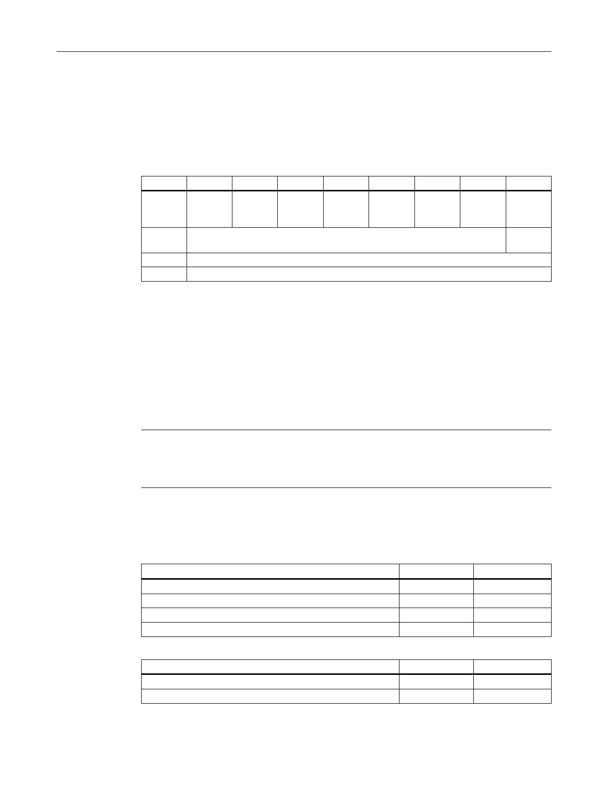
Parameters are assigned to the operating mode via the m+0 byte (Analog Control Byte 0) of
the output image of the analog outputs:
Byte Bit7 Bit6 Bit5 Bit4 Bit3 Bit3 Bit1 Bit0
m+0 AO
(channel
4)
AO
(channel
4)
AO
(channel
3)
AO
(channel
3)
AI
(channel
2)
AI
(channel
2)
AI
(channel
1)
AI
(channel
1)
m+1 Reserved Data for‐
mat
m+2 Reserved
m+3 Reserved
The reserved bits must be preassigned with the value "0".
The operating mode is set to "no operating mode" during power-up, as soon as a valid setting
is made this will be applied and will subsequently no longer be reset. If a reset is initiated by
the user, this is interpreted as an error.
Type of control
The control type must be specified in the Analog Control Byte m+1 (bit 0), so that the 16 bit
input and output values from and for the analog module are correctly interpreted by the control.
In the SINUMERIK 828D control, the value "1" must be entered.
Note
The control type must be set prior to the operating mode so that the first set of user data is not
misinterpreted. In addition to this, the Analog Control Byte m+0 / m+1 must only be accessed
byte by byte.
Assigning parameters to the analog inputs
The analog inputs (AI) can be operated in the following operating modes:
Operating mode 1st channel Bit 1 Bit 0
No operating mode 0 0
Voltage measurement 0 1
Current measurement 1 0
Temperature measurement (Pt100) 1 1
Operating mode 2nd channel Bit 3 Bit 2
No operating mode 0 0
Voltage measurement 0 1
Anschließbare Komponenten
7.9 PP 72/48D 2/2A PN
PPU and components
Manual, 05/2015, 6FC5397-2DP40-3BA4 237

 Loading...


