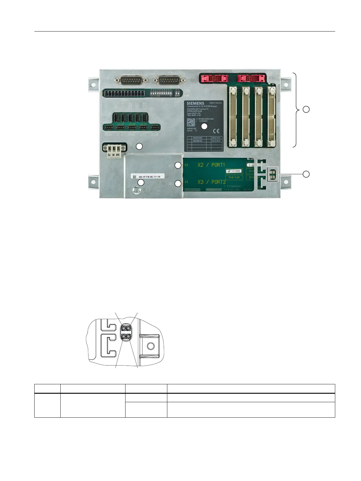
Illustration
① Type plate
② Terminal strips / connectors for operator controls
③ Diagnostics LED
④ PROFINET interface X2 (Industrial Ethernet 100 Mbit/s)
⑤ PROFINET interface X3 (Industrial Ethernet 100 Mbit/s)
⑥ Grounding screw M5 for potential equalization connection
⑦ 24 V DC power supply X1 (with screw connection)
Figure 7-27 View of MCP Interface PN
LED displays
Name Function Status Meaning
H500 POWER OK (green) Lit All internal voltages are in the setpoint range.
Not lit At least one of the generated voltages has exceeded its setpoint; a
reset will be initiated.
Anschließbare Komponenten
7.5 MCP Interface PN
PPU and components
Manual, 05/2015, 6FC5397-2DP40-3BA4 155

 Loading...


