Table 7-36 X41 pin assignments
Pin Signal name Type Meaning
1 DI125.5
I
24 V input 3
2 DI125.6 24 V input 4
3 DI125.7 24 V input 5
4 M V Ground
Table 7-37 Technical data for X40, X41
Parameter Value
Voltage: -3 V to 30 V
Typical current consumption: 6 mA at 24 VDC
Signal level (including ripple): High signal level: 15 V to 30 V
Low signal level: -3 V to 5 V
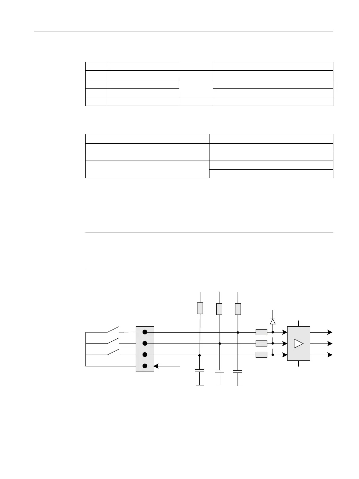
Digital inputs X51, X52, X55
Only switches (passive inputs) may be connected via the X51, X52 and X55 connectors.
Typically, illuminated pushbuttons are connected here. The lamps in the buttons are activated
via X53, X54 and X56 to X58.
Note
Connection miniature handheld unit
Alternatively, at the inputs X51, X52 and X55, one miniature handheld unit may be operated.
For details, please refer to Section Mini handheld unit, Connecting (Page 185).
9
9
9
;
',
',
',
N
N
0
0
000
Q)
Figure 7-31 Block diagram X51, X52, X55
Anschließbare Komponenten
7.5 MCP Interface PN
PPU and components
Manual, 05/2015, 6FC5397-2DP40-3BA4 159

 Loading...


