Digital outputs
To supply (24 V DC) the digital outputs, an additional external power supply source is required.
The power supply is connected to terminals X111, X222 and X333 via pins 47, 48, 49 and 50
(DOCOMx). Ground pins must be connected to a common chassis ground.
Maximum current consumption: 3 x 4 A if all outputs are used simultaneously.
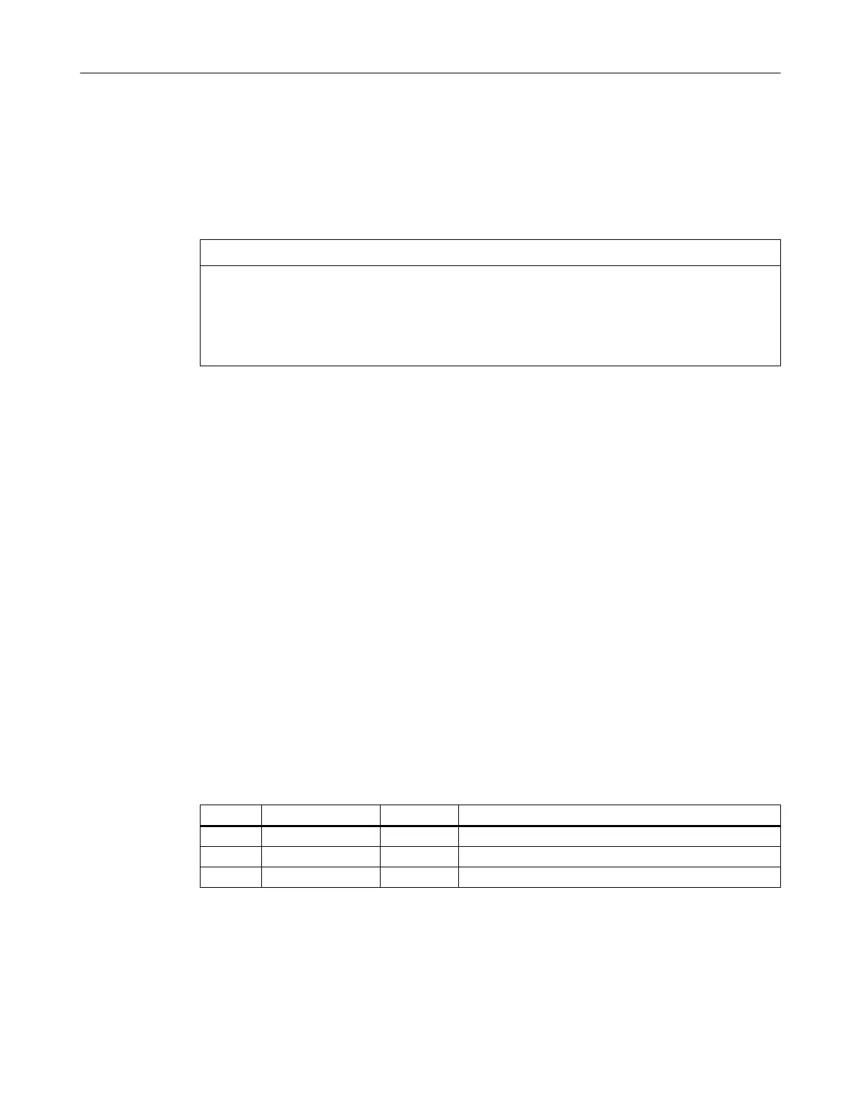
NOTICE
Protection against short circuit
It is the user's responsibility to ensure that the max. current consumption per DOCOMx pin
(X111, X222, X333: Pins 47, 48, 49, 50) does not exceed 1 A. The power supply (+24 V DC)
for the digital outputs must therefore be connected to all 4 pins per DOCOMx (X111, X222,
X333: pins 47, 48, 49, 50).
Analog inputs/outputs
The inputs and outputs are supplied with power on-board, i.e. no further external power supply
units are required.
Wiring the power supply
Properties
This interface is intended exclusively for the connection of the external 24 V power supply.
On the module side, the power supplies are protected against:
● Polarity reversal
● Short-circuit (elec. current limitation of the outputs)
● Overload (self-restoring PTC fuse - Multifuse)
Pin assignment
Table 7-68 Pin assignment at X1 screw-type terminal block
Pin Signal name Signal type Meaning
1 P24 VI 24 VDC power supply
2 M GND Ground
3 PE GND Protective ground
Power requirement
0.7 A (at 24 V DC) for PP 72/48D 2/2A PN and digital inputs plus 3 x 4 A at X111, X222 and
X333 for supplying digital outputs.
Anschließbare Komponenten
7.8 PP 72/48D PN
PPU and components
Manual, 05/2015, 6FC5397-2DP40-3BA4 199

 Loading...


