Pin assignment
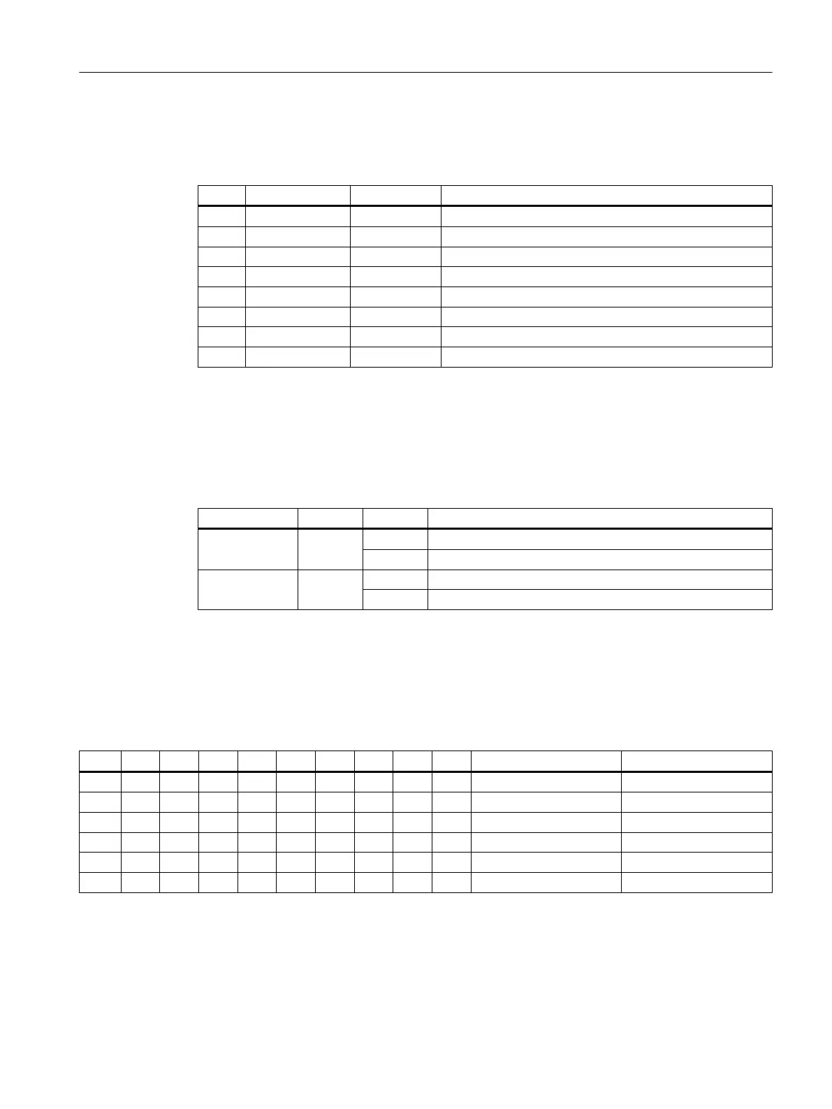
Table 7-70 Pin assignment - PROFINET X2, Port 1 and Port 2
Pin Signal name Signal type Meaning
1 TX+ O Transmit data +
2 TX- O Transmit data -
3 RX+ I Receive data +
4 N.C. - Not assigned
5 N.C. - Not assigned
6 RX- I Receive data -
7 N.C. - Not assigned
8 N.C. - Not assigned
LED displays
For diagnostic purposes, the RJ45 sockets are each equipped with a green and a yellow LED.
This allows the following information on the respective PROFINET port to be displayed:
Table 7-71 PROFINET ports LED displays
Name Color Status Meaning
Link Green Lit 100 Mbit link available
Off Missing or faulty link
Activity Yellow Lit Sending or receiving
Off No activity
PROFINET address (S1)
The right logical address must be assigned to the I/O module for communication with PLC I/O
interface using the 10 bit DIP switch S1.
Table 7-72 Switch S1 settings
1 2 3 4 5 6 7 8 9 10 Device name Meaning
ON ON
ON OFF OFF ON OFF OFF OFF OFF pp72x48pn9 1st PP module
OFF OFF OFF ON OFF OFF OFF OFF pp72x48pn8 2nd PP module
ON ON ON OFF OFF OFF OFF OFF pp72x48pn7 3rd PP module
OFF ON ON OFF OFF OFF OFF OFF pp72x48pn6 4th PP module
ON OFF ON OFF OFF OFF OFF OFF pp72x48pn5 5th PP module
The device name consists of the PROFINET name and the device number: in the case of I/O modules, the 1st module is device
number 9.
Anschließbare Komponenten
7.8 PP 72/48D PN
PPU and components
Manual, 05/2015, 6FC5397-2DP40-3BA4 201

 Loading...


