Wiring analog inputs/outputs
Procedure:
1. Strip cable for analog signals.
2. Secure the stripped connection piece of the cable with the shield connection clamp.
NOTICE
Shield contact
If the analog inputs/outputs are wired, a shielded lead must be used. The shield must be
supported.
X3 pin assignment
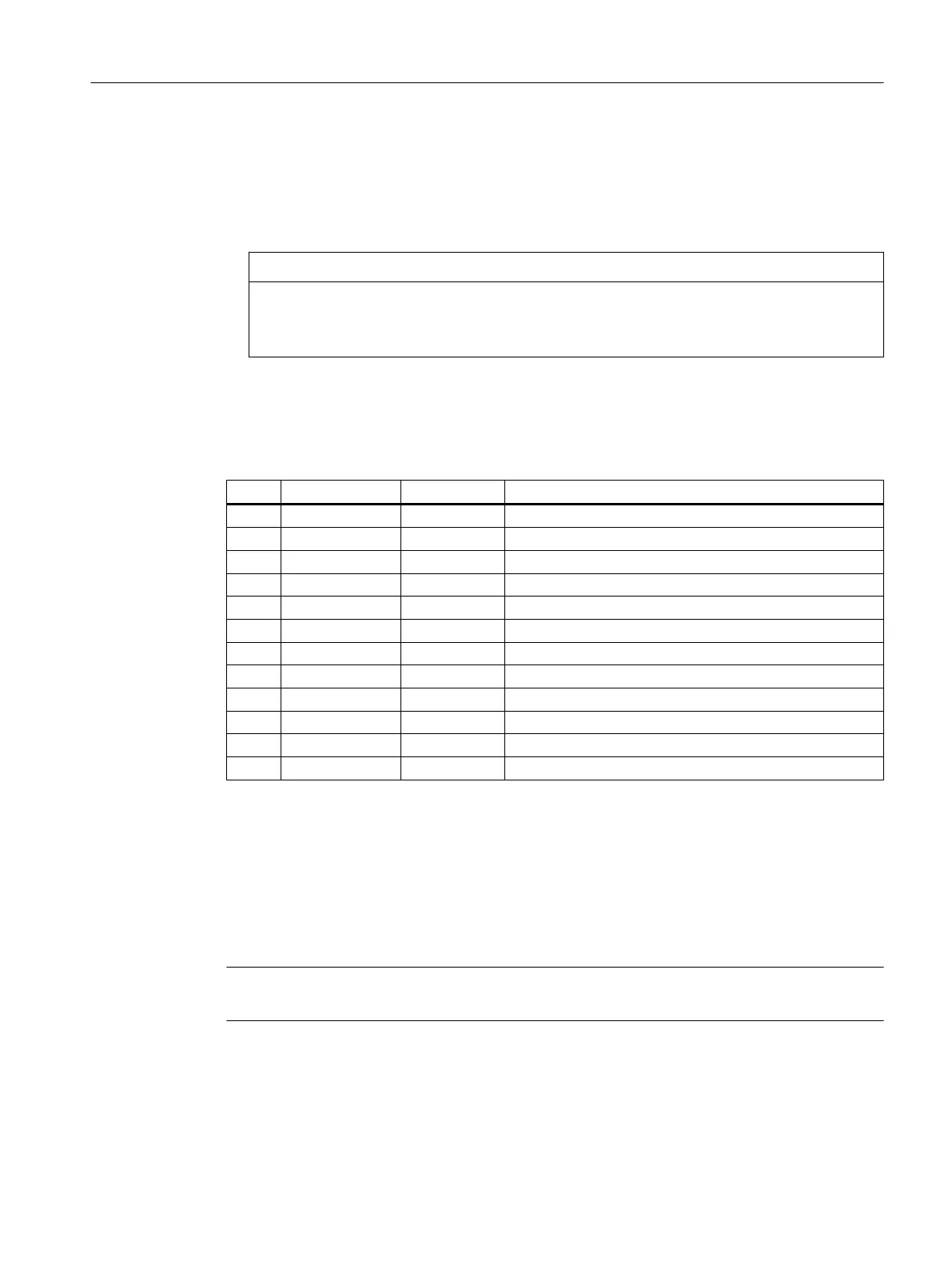
Table 7-98 Pin assignment (standard)
Pin Signal name Signal type Meaning
1 CO1 O Channel 1 current output for PT100
2 CI1 I Channel 1 current input for PT100
3 AI1+ I Channel 1 analog input +
4 AI1- I Channel 1 analog input -
5 CO2 O Channel 2 current output for PT100
6 CI2 I Channel 2 current input for PT100
7 AI2+ I Channel 2 analog input +
8 AI2- I Channel 2 analog input -
9 AO3+ O Channel 3 current and voltage output +
10 AO3- O Channel 3 current and voltage output -
11 AO4+ O Channel 4 current and voltage output +
12 AO4- O Channel 4 current and voltage output -
The analog signal to be measured is connected to the terminals AI 1+/- and AI 2+/-. AI stands for "Analog
Input". The CO "Current Output" and CI "Current Input" terminals supply the constant current for the 4-
wire measurement of PT100 elements.
Analog inputs
The module has two analog inputs. These can optionally be assigned parameters as voltage,
current or PT100 input.
Note
The analog inputs are only enabled following the parameter assignment.
Anschließbare Komponenten
7.9 PP 72/48D 2/2A PN
PPU and components
Manual, 05/2015, 6FC5397-2DP40-3BA4 229

 Loading...


