Byte Bit7 Bit6 Bit5 Bit4 Bit3 Bit3 Bit1 Bit0
m+5 AI 0.7 AI 0.6 AI 0.5 AI 0.4 AI 0.3 AI 0.2 AI 0.1 AI 0.0
m+6 AI 1.15 AI 1.14 AI 1.13 AI 1.12 AI 1.11 AI 1.10 AI 1.9 AI 1.8
m+7 AI 1.7 AI 1.6 AI 1.5 AI 1.4 AI 1.3 AI 1.2 AI 1.1 AI 1.0
Output image
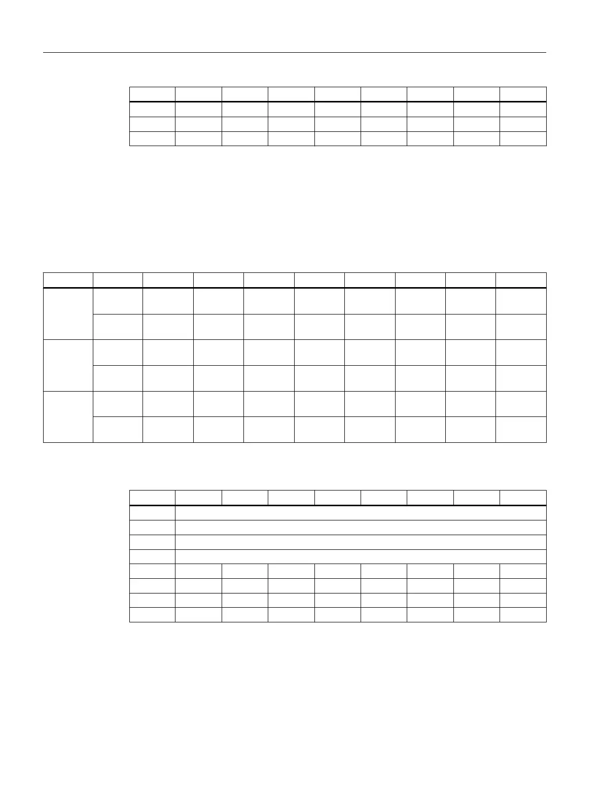
The image comprises 2 slots (n, m, ≙ start address):
● Slot 1: Digital outputs (DO): n+0 … n+5 (6 byte)
● Slot 2: 2 analog outputs (AO): m+0 … m+7 (8 byte)
Table 7-106 Output image of digital outputs for the 1st I/O module (n=0)
Terminal Byte Bit7 Bit6 Bit5 Bit4 Bit3 Bit2 Bit1 Bit0
X111
n+0 Pin38
DO 0.7
Pin37
DO 0.6
Pin36
DO 0.5
Pin35
DO 0.4
Pin34
DO 0.3
Pin33
DO 0.2
Pin32
DO 0.1
Pin31
DO 0.0
n+1 Pin46
DO 1.7
Pin45
DO 1.6
Pin44
DO 1.5
Pin43
DO 1.4
Pin42
DO 1.3
Pin41
DO 1.2
Pin40
DO 1.1
Pin39
DO 1.0
X222
n+2 Pin38
DO 2.7
Pin37
DO 2.6
Pin36
DO 2.5
Pin35
DO 2.4
Pin34
DO 2.3
Pin33
DO 2.2
Pin32
DO 2.1
Pin31
DO 2.0
n+3 Pin46
DO 3.7
Pin45
DO 3.6
Pin44
DO 3.5
Pin43
DO 3.4
Pin42
DO 3.3
Pin41
DO 3.2
Pin40
DO 3.1
Pin39
DO 3.0
X333
n+4 Pin38
DO 4.7
Pin37
DO 4.6
Pin36
DO 4.5
Pin35
DO 4.4
Pin34
DO 4.3
Pin33
DO 4.2
Pin32
DO 4.1
Pin31
DO 4.0
n+5 Pin46
DO 5.7
Pin45
DO 5.6
Pin44
DO 5.5
Pin43
DO 5.4
Pin42
DO 5.3
Pin41
DO 5.2
Pin40
DO 5.1
Pin39
DO 5.0
Table 7-107 Output image of analog outputs for the 1st I/O module (m=56)
Byte Bit7 Bit6 Bit5 Bit4 Bit3 Bit3 Bit1 Bit0
m+0 Analog Control Byte 0
m+1 Analog Control Byte 1
m+2 Analog Control Byte 2
m+3 Analog Control Byte 3
m+4 AO 0.15 AO 0.14 AO 0.13 AO 0.12 AO 0.11 AO 0.10 AO 0.9 AO 0.8
m+5 AO 0.7 AO 0.6 AO 0.5 AO 0.4 AO 0.3 AO 0.2 AO 0.1 AO 0.0
m+6 AO 1.15 AO 1.14 AO 1.13 AO 1.12 AO 1.11 AO 1.10 AO 1.9 AO 1.8
m+7 AO 1.7 AO 1.6 AO 1.5 AO 1.4 AO 1.3 AO 1.2 AO 1.1 AO 1.0
See also
Information on settings in the machine data can be found in Section Activating components
(Page 255).
Anschließbare Komponenten
7.9 PP 72/48D 2/2A PN
PPU and components
234 Manual, 05/2015, 6FC5397-2DP40-3BA4

 Loading...


