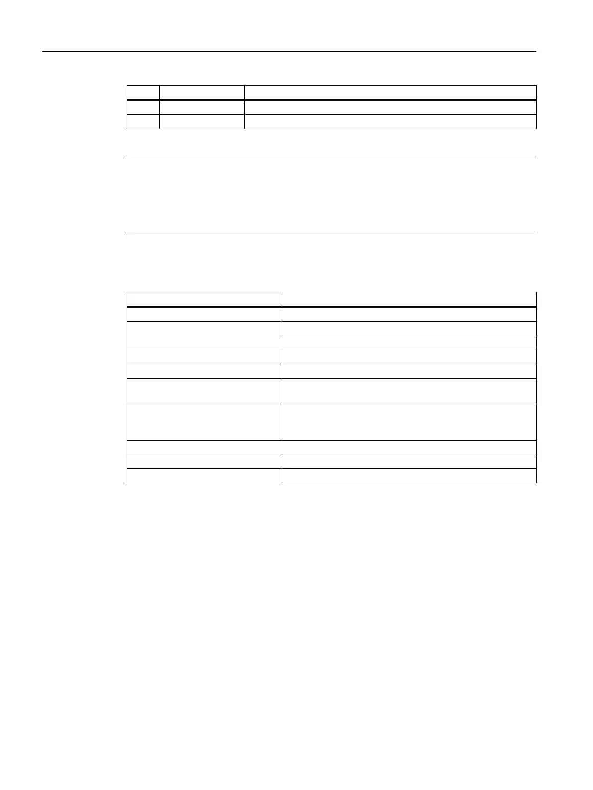
Pin Signal name Meaning
13 DI/DO11 Digital input/output 11 (rapid input)
14 M Ground
An open input is interpreted as "low".
Note
Terminal M1 must be connected for the digital inputs (DI) 0 to 3 and 16/17 to function. This
can be done as follows:
● Connect the ground reference of the digital inputs.
● Jumper to terminal M: This removes the electrical isolation for these digital inputs.
Table 7-121 Technical data for X122
Parameter Value
Current consumption Typical: 10 mA at 24 V DC
Galvanic isolation The reference potential is terminal M1
As an input
Voltage -3 V to 30 V
Current consumption Typical: 10 mA at 24 V DC
Signal level (including ripple) High signal level: 15 V to 30 V
Low signal level: -3 V to 5 V
Signal propagation times Inputs / "fast inputs":
L → H: approx. 50 μs/5 μs
H → L: approx. 100 μs/50 μs
As an output
Voltage 24 V DC
Max. load current Per output: 500 mA continuous short circuit-proof
Anschließbare Komponenten
7.10 NX10.3
PPU and components
252 Manual, 05/2015, 6FC5397-2DP40-3BA4

 Loading...


