● The motor encoder must be connected to the associated power unit.
Component Connecting the motor encoder via DRIVE-CLiQ
Single Motor Module booksize X202
Double Motor Module booksize
● Motor connection X1: Encoder at X202
● Motor connection X2: Encoder at X203
Single Motor Module chassis X402
Power Module chassis X402
Note
If an additional encoder is connected to a Motor Module, it is assigned to this drive as encoder
2 in the automatic configuration. At a Double Motor Module, an encoder at X201 is assigned
to the 2nd feedrate as 2nd measuring system.
960
338
;
;
;
$FWLYH
/LQH
0RGXOH
;;;;
;;;;
;;;;
;
6LQJOH
0RWRU
0RGXOH
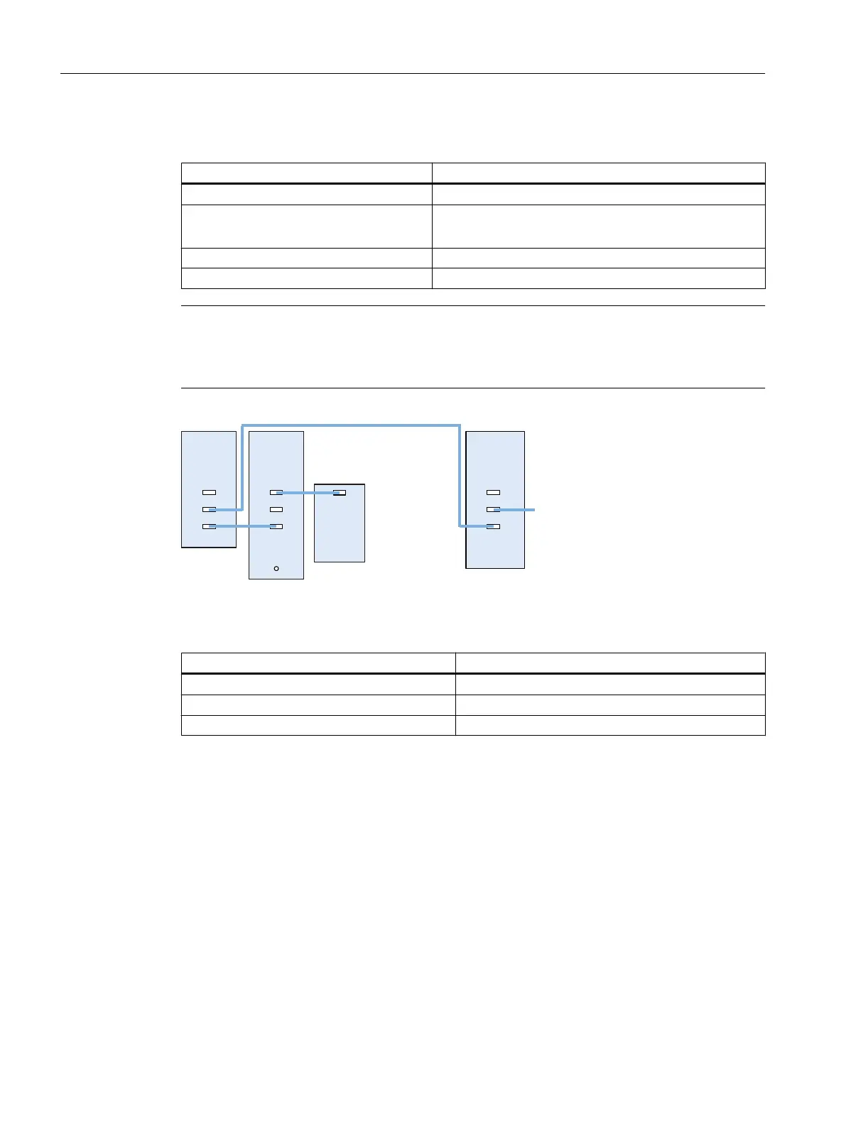
Figure 5-3 Example: Topology with VSM for booksize and chassis components
Component VSM connection
Active Line Module booksize X202
Active Line Module (chassis) X402
Power Modules The VSM is not supported.
Rules for permitted topologies
5.2 Topology rules for S120 Booksize
PPU and components
58 Manual, 05/2015, 6FC5397-2DP40-3BA4

 Loading...


