The extent of the interlocking checks is determined by the configuration and interlocking logic of the relay.
For more information on GOOSE messaging, please refer to the SIPROTEC 4 System Description.
Switching objects that require system interlocking in a central control system are marked by a specific param-
eter inside the bay unit (via configuration matrix).
For all commands, operation with interlocking (normal mode) or without interlocking (test mode) can be
selected:
•
For local commands by reprogramming the settings with password check,
•
For automatic commands, via command processing by CFC and Deactivated Interlocking Recognition,
•
For local/remote commands, using an additional interlocking disable command via PROFIBUS.
Interlocked/non-interlocked Switching
The configurable command checks in the SIPROTEC 4 devices are also called “standard interlocking”. These
checks can be activated via DIGSI (interlocked switching/tagging) or deactivated (non-interlocked).
De-interlocked or non-interlocked switching means that the configured interlock conditions are not tested.
Interlocked switching means that all configured interlocking conditions are checked within the command
processing. If a condition could not be fulfilled, the command will be rejected by an indication with a minus
added to it, e.g. “CO–”, followed by an operation response information. The command is rejected if a
synchronism check is carried out before closing and the conditions for synchronism are not fulfilled.
Table 2-18 shows some types of commands and indications. The indications marked with *) are displayed only
in the event logs on the device display; for DIGSI they appear in spontaneous indications.
Table 2-18 Command types and corresponding indications
Type of Command Control Cause Indication
Control issued Switching CO CO+/–
Manual tagging (positive/negative) Manual tagging MT MT+/–
Information state command, Input blocking Input blocking ST ST+/– *)
Information state command, Output blocking Output blocking ST ST+/– *)
Cancel command Cancel CA CA+/–
The plus sign in the indication is a confirmation of the command execution: The command output has a posi-
tive result, as expected. A minus sign means a negative, i.e. an unexpected result. The command was rejected.
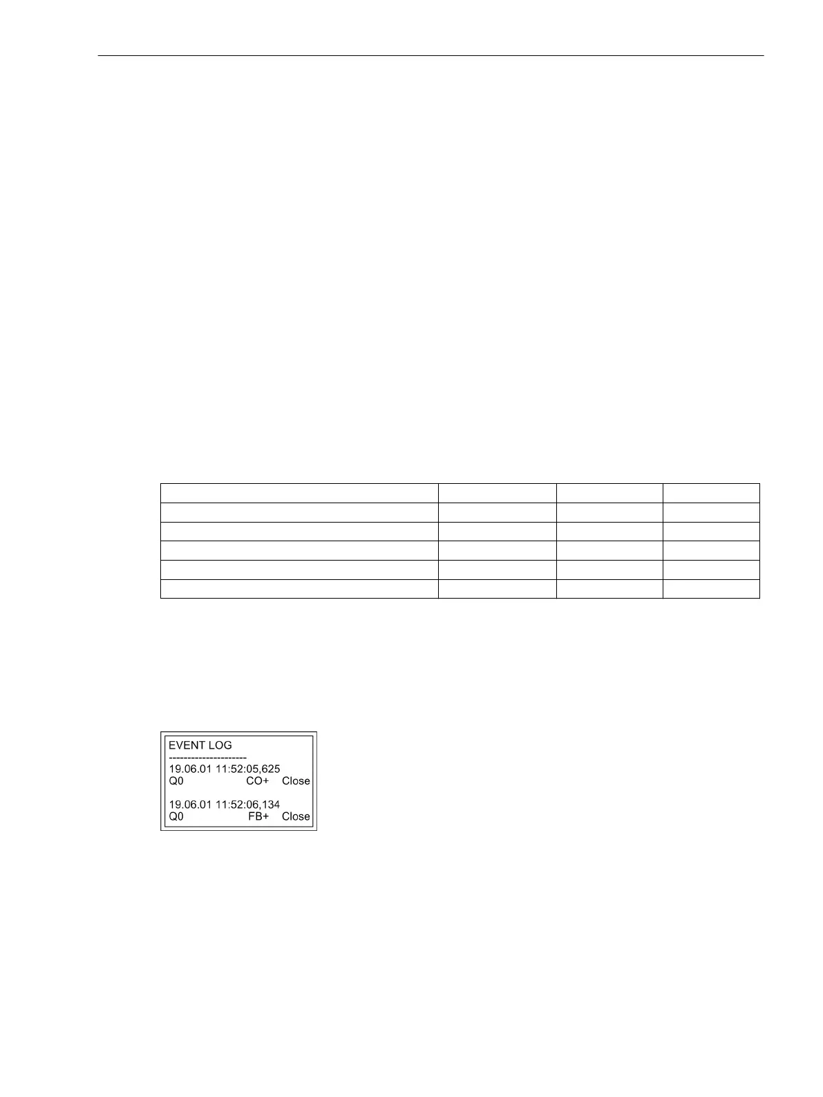
Figure 2-129 shows an example for successful switching of the circuit breaker in the Event Log (command and
feedback).
The check of interlocking can be programmed separately for all switching devices and tags that were set with
a tagging command. Other internal commands such as overriding or abort are not tested, i.e. are executed
independently of the interlockings.
[leistungsschalterbetriebsmeldung-020315-wlk, 1, en_GB]
Figure 2-129 Example of an operational indication for switching circuit breaker (Q0)
Standard Interlocking
The standard interlocking includes the checks for each switchgear which were set during the configuration of
inputs and outputs, see SIPROTEC 4 System Description.
An overview for processing the interlocking conditions in the relay is shown in Figure 2-130.
Functions
2.24 Command Processing
SIPROTEC 4, 7UT6x, Manual 305
C53000-G1176-C230-5, Edition 09.2016
 Loading...


