[standardveriegelungen-wlk-020802, 1, en_GB]
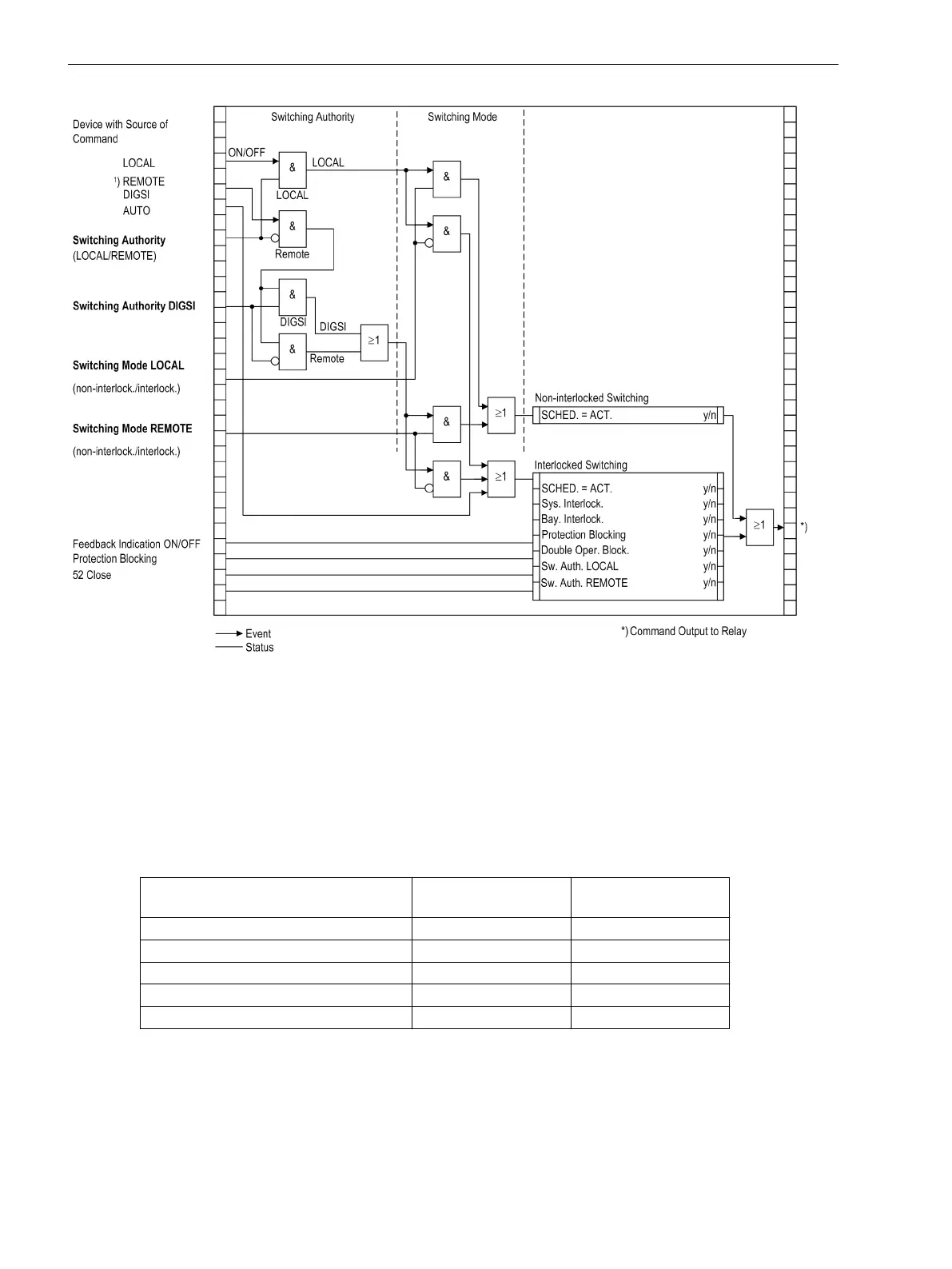
Figure 2-130
Standard interlockings
1) Source of Command REMOTE includes LOCAL.
(NAH Command using substation controller
FERN Command via telecontrol station to power system management and from power system manage-
ment to the device)
The display shows the configured interlocking reasons. They are marked by letters as explained in Table 2-19 .
Table 2-19
Interlocking Commands
Interlocking Commands Command (abbrevia-
tion)
Display
Control Authority SV S
System Interlocking AV A
Bay Interlocking BI F
SET = ACTUAL (switch direction check)
SΙ Ι
Protection Blockage SB B
Figure 2-131 shows all interlocking conditions (which usually appear in the display of the device) for three
switchgear items with the relevant abbreviations explained in Table . Table 2-19 explained abbreviations. All
parameterized interlocking conditions are indicated.
Functions
2.24 Command Processing
306 SIPROTEC 4, 7UT6x, Manual
C53000-G1176-C230-5, Edition 09.2016
 Loading...


