The relay contacts for binary outputs BO1 through BO5 can be connected to common potential, or configured
individually for BO1, BO4 and BO5 (BO2 and BO3 are without function in this context) (see also General
Diagrams in the Appendix B Terminal Assignments).
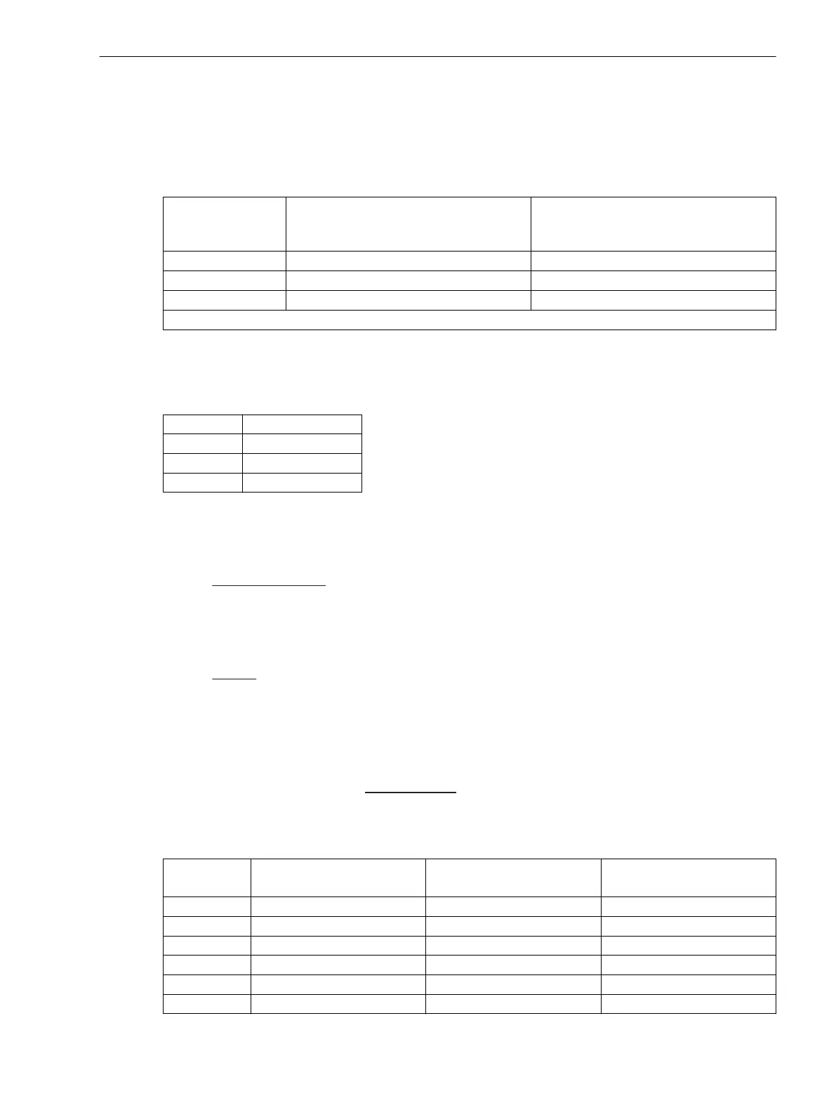
Table 3-16 Jumper settings for the configuration of the Common Potential of BO1 through BO5 or for
configuration of BO1, BO4 and BO5 as Single Relays
Jumper BO1 to BO5
connected to common potential
1)
BO1, BO4, BO5 configured as single
relays
(BO2 and BO3 without function)
X80 1-2, 3-4 2-3, 4-5
X81 1-2, 3-4 2-3, 4-5
X82 2-3 1-2
1)
Delivery state
Jumpers X71 through X73 on the input/output board C-I/O-2 serve for setting the bus address. Their position
may not be changed. The following table shows the preset jumper positions.
Table 3-17 Jumper Position of the Module Addresses of the input/output board C-I/O-2
Jumper Presetting
X71 1-2 (H)
X72 1-2 (H)
X73 2-3 (L)
The rated currents of the measured current inputs can be determined for each analogue input via jumpers.
With default settings all jumpers are set to the same rated current (according to the order number of the
device).
The input/output board C-I/O-2 carries the following measured current inputs:
•
For
3-phase applications and 1-phase transformers:
There are 3 measuring inputs for the three-phase measuring location M3: Ι
L1M3
, Ι
L2M3
, Ι
L3M3
. The jumpers
X61, X62, X63 belonging to this measuring location must be plugged all to the rated secondary current
of the connected current transformers: “1A” or “5A”). Furthermore, the corresponding common jumpers
(X51 and X60) have to be plugged to the same rated current.
•
For 1-phase busbar protection:
There are 3 measuring inputs for 3 different measuring locations, i.e. the feeders 7 to 9: Ι
7
, Ι
8
, Ι
9
. Each
input can be set individually (X61, X62, X63) to “1A”, “5A” or “0.1A”. Only if the measuring inputs Ι7 to Ι9
have the same rated current, the common jumpers X60 are plugged to this rated current.
If different rated currents (X51 and X60) are reigning within the input group, the position of the common
jumpers (X51 and X60) is irrelevant.
•
For the additional single-phase
measuring input Ι
Z2
:
Jumper X64 is set to the required rated current for this 1-phase current input: “1A” oder “5A”.
Table 3-18
Jumper setting for Rated current or Measuring range
Jumper Rated current 0.1 A
Measuring range 10 A
Rated current 1 A
Measuring range 100 A
Rated current 5 A
Measuring range 500 A
X51 2-3 1-2 1-2
X60 1-2 1-2 2-3
X61 1-5 3-5 4-5
X62 1-5 3-5 4-5
X63 1-5 3-5 4-5
X64 1-5 3-5 4-5
Mounting and Commissioning
3.1 Mounting and Connections
SIPROTEC 4, 7UT6x, Manual 331
C53000-G1176-C230-5, Edition 09.2016

 Loading...


