Both of the following tables show which version of configuration is supported for Autotransf. and for a
Autotr. node and which principle of the transformer is applied. The earth winding is included as a side due
to the parameterisation.
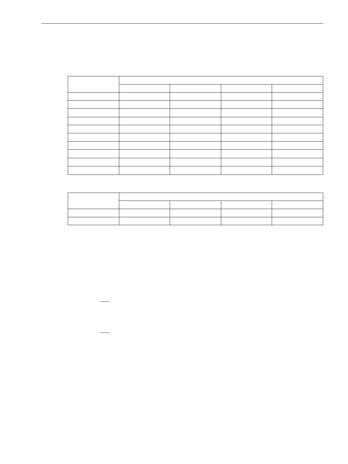
Table 2-2 Configuration Versions in an Autotransf.
Number
of sides
Configuration types of the side
SIDE 1 SIDE 2 SIDE 3 SIDE 4
2
auto-connected auto-connected
— —
3
auto-connected auto-connected auto-connected
—
3
auto-connected auto-connected
compensation.
—
3
auto-connected auto-connected earth.electrode
—
4
auto-connected auto-connected auto-connected auto-connected
4
auto-connected auto-connected auto-connected
compensation.
4
auto-connected auto-connected auto-connected earth.electrode
4
auto-connected auto-connected
compensation.
auto-connected
4
auto-connected auto-connected
compensation. compensation.
4
auto-connected auto-connected
compensation.
earth.electrode
Table 2-3 Configuration Versions in anAutotr. node
Number
of sides
Configuration types of the side
SIDE 1 SIDE 2 SIDE 3 SIDE 4
3
auto-connected auto-connected earth.electrode
—
4
auto-connected auto-connected auto-connected earth.electrode
Address 241 SIDE 1 of the auto-transformer must be assigned to a auto-connected (primary winding, as
recommended above). This is imperative and, therefore, cannot be changed.
Address 242 SIDE 2 of the auto-transformer must also be assigned to an auto-connected (secondary tap
as recommended above). This is imperative and, therefore, cannot be changed.
For the sides 3 and 4, alternatives exist. If the auto-transformer provides another tap, the side thereof is
declared as aauto-connected.
In the example in Figure 2-6 is for a PROT. OBJECT = Autotransf. the side S3 the tertiary winding, thus
the accessible and load capable compensation winding. In this example the setting would be:
Address 243 SIDE 3 = compensation.
This option is
only possible for PROT. OBJECT = Autotransf..
In the examples of Figure 2-7 for PROT. OBJECT = Autotr. node side 3 is facing the earthing electrode of
the transformer. Here:
Address 243 SIDE 3 = earth.electrode.
This option is only possible if PROT. OBJECT =Autotransf. or if PROT. OBJECT = Autotr. node, if no
further side has been assigned.
The same applied to address 244 SIDE 4 = earth.electrode
In summary we can say: the sides S1 and S2 are imperatively assigned to the connections of the auto-
connected winding. For SIDE 3 and SIDE 4 you have to select the option corresponding to the topology:
auto-connected (for another tap of the auto-connected winding), compensation (for an accessible and
load-capable compensation winding) or earth.electrode (for the earthed side of the auto-connected
windings).
Assignment of Auxiliary 1-phase Measuring Locations
Each of the auxiliary (1-phase) current inputs must now be assigned in the addresses 251 to 254. The number
of auxiliary inputs depends on the device type (see Table 2-1). In 7UT635 all inputs ΙX1 to ΙX3 are only avail-
able as additional 1-phase measuring inputs if they are not needed for a fifth 3-phase measuring location, i.e.
if only four 3-phase measuring locations are needed.
Functions
2.1 General
SIPROTEC 4, 7UT6x, Manual 51
C53000-G1176-C230-5, Edition 09.2016

 Loading...


